Home / Products / Ultrasonic Level Meter
Back to Products
Ultrasonic Level Meter
Level Instruments

Ultrasonic Level Meter

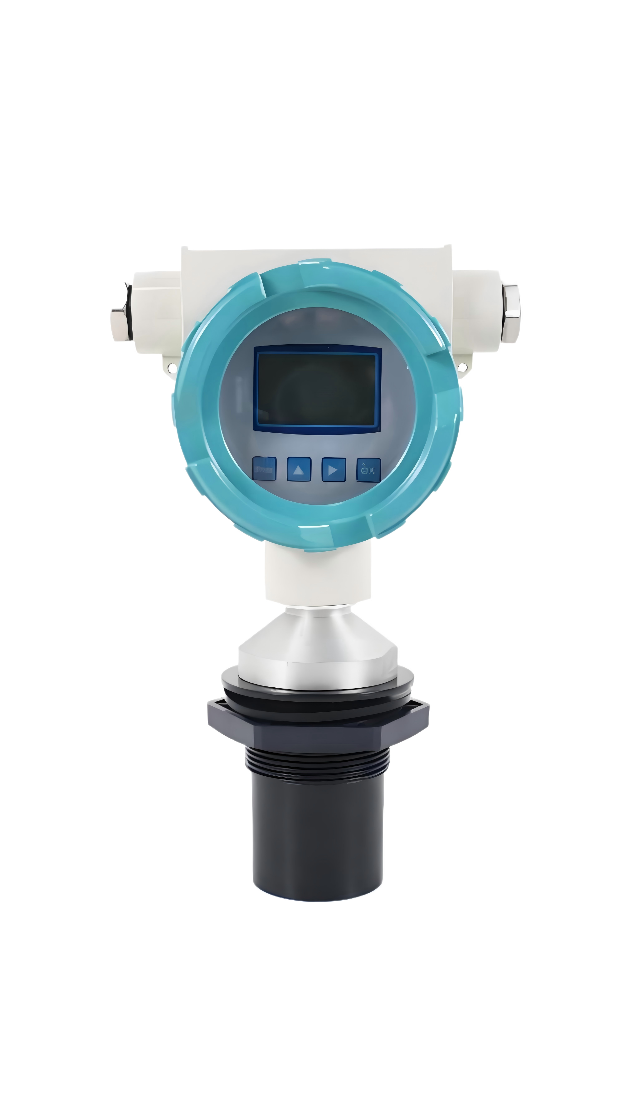
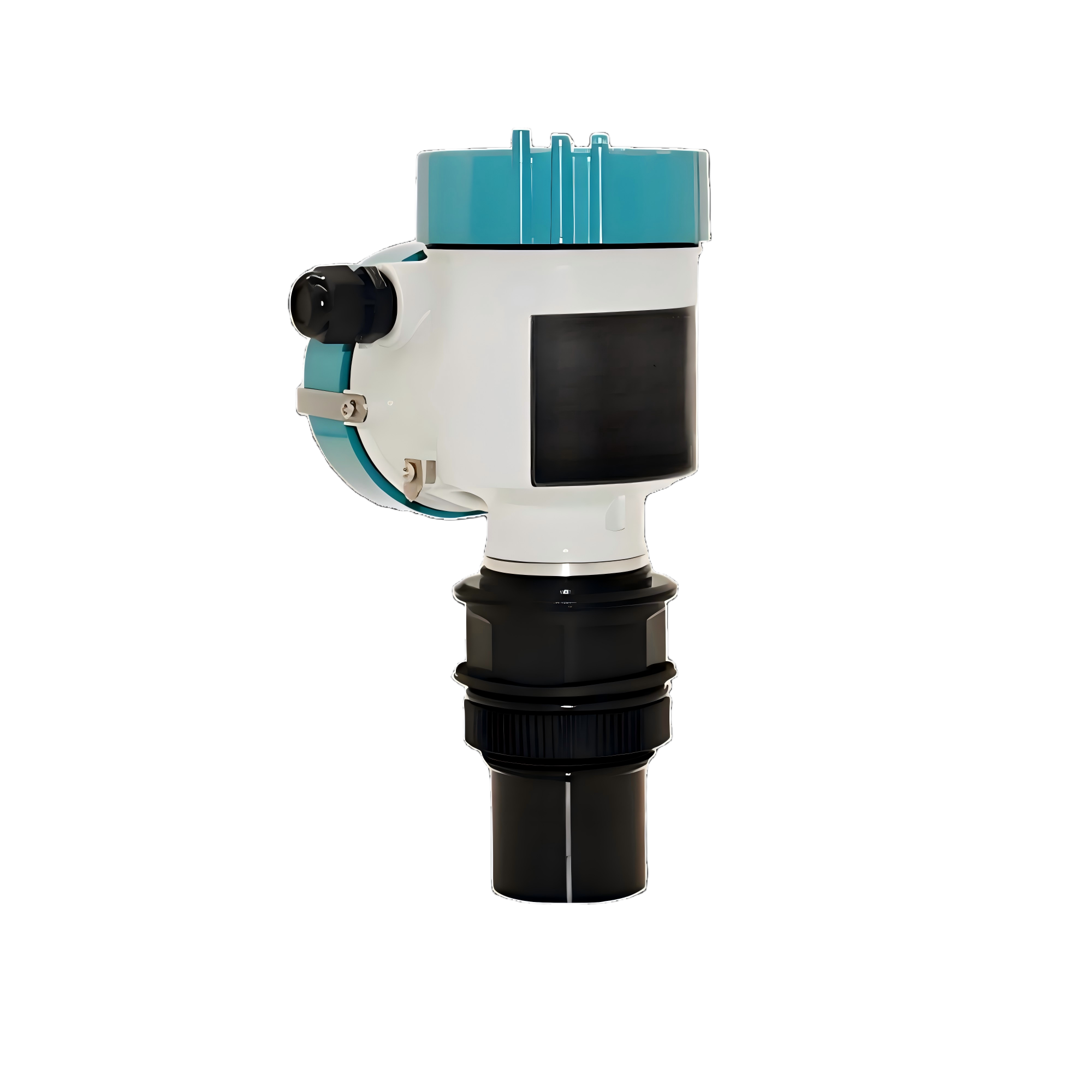
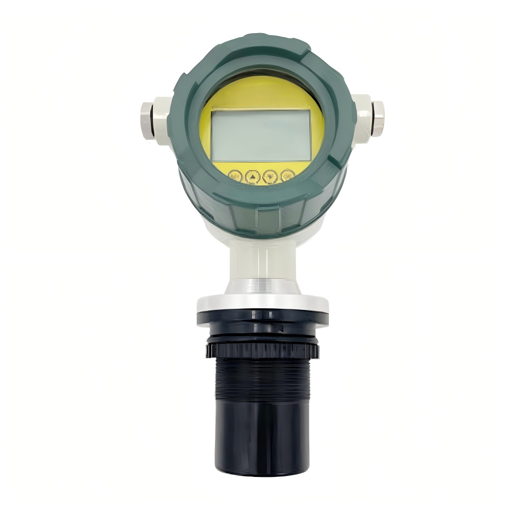
The ultrasonic level meter is an instrument that utilizes ultrasonic technology for liquid level measurement. It is primarily controlled by a single-c...

Performance Metrics

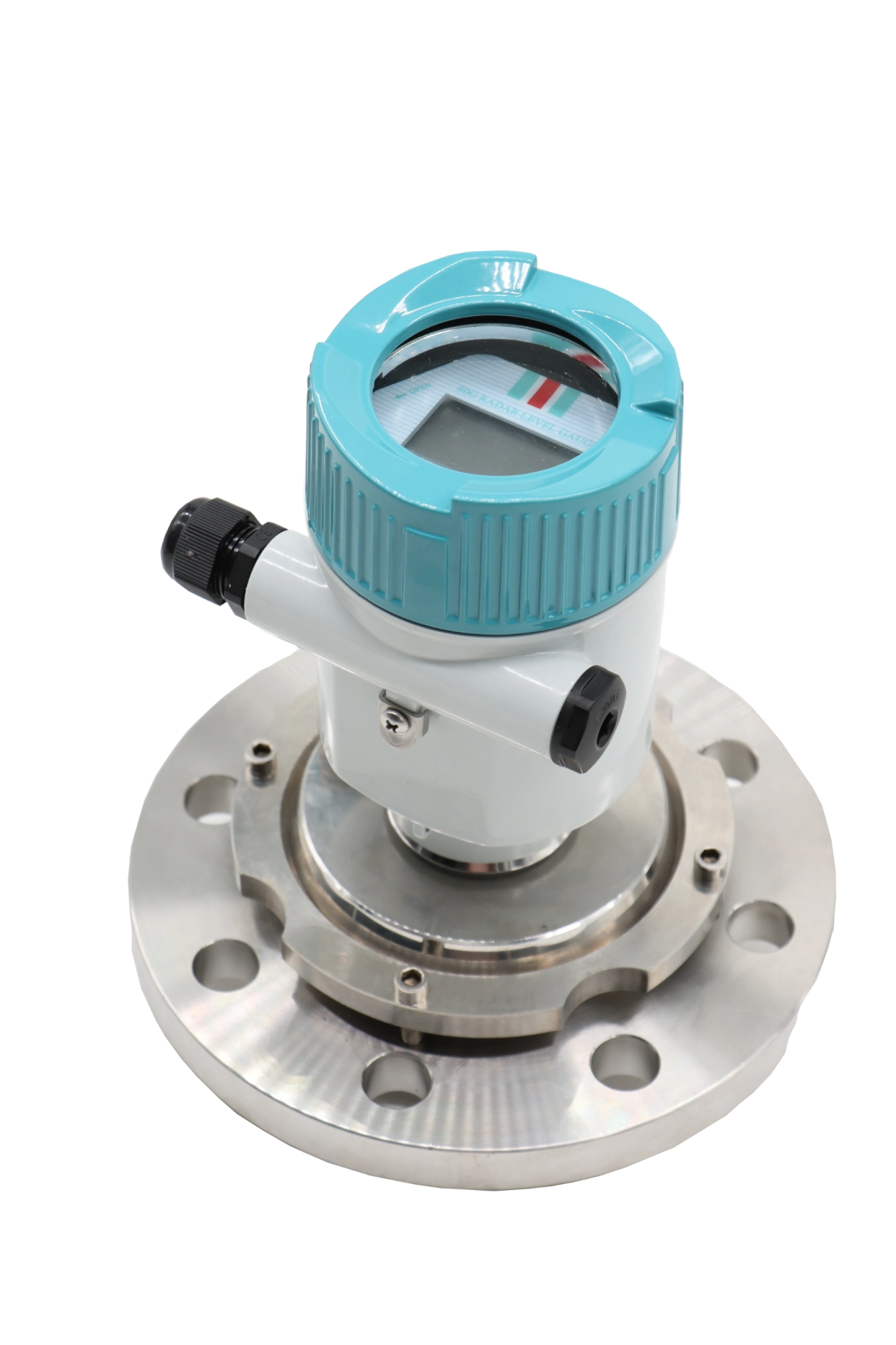
Process Connection Thread or Flange (Optional)
Protection Rating IP65
Blind Zone 0.3m ~ 0.6m
Output Signal 4~20mA

Key Features

Automatic power adjustment, gain control, and temperature compensation
Advanced detection technology and rich software functions adapt to various complex environments
Utilizes new waveform calculation technology to improve measurement accuracy
Interference echo suppression function ensures authentic measurement data
Non-contact measurement suitable for various liquids and solid materials
High-reliability design for environmental protection, water conservancy, chemical, and metallurgical industries

Ultrasonic Level Meter: Non-Contact Measurement Solution

The Ultrasonic Level Meter is a versatile and reliable instrument for measuring the height or level of various liquids and solid materials. It operates on a non-contact principle, making it ideal for demanding applications in environmental protection, water conservancy, chemical, and metallurgical industries.

Ultrasonic Level Meter working principle diagram

How the Ultrasonic Level Meter Works

In measurement, pulsed ultrasonic waves are emitted by the sensor (transducer), reflected by the surface of the object, and then received by the same sensor, converting them into electrical signals.

The distance from the sensor to the measured object is calculated based on the time between the emission and reception of the sound waves. This precise time-of-flight calculation is the core of its operation.

Core Advantages of Ultrasonic Level Measurement

Universal Application

Due to its non-contact measurement method, the measured medium is almost unrestricted. This makes the ultrasonic level sensor widely applicable for measuring the height of various liquids and solid materials.

High Reliability Design

Engineered for harsh industrial environments, our ultrasonic level gauges offer high-reliability performance in sectors like chemical processing and metallurgy.

Ultrasonic Level Meter installation in industrial setting

Advanced Technology for Complex Environments

The meter features automatic power adjustment, gain control, and temperature compensation. These functions ensure stable readings despite changing environmental conditions.

Advanced detection technology and rich software functions allow the device to adapt to various complex industrial environments, providing consistent and trustworthy data.

Key Features and Technical Capabilities

Ultrasonic Level Meter accuracy and echo suppression feature

Enhanced Accuracy and Data Integrity

The utilization of new waveform calculation technology significantly improves the measurement accuracy of the liquid level sensor or solid material level sensor.

An intelligent interference echo suppression function is integrated to filter out false signals, ensuring the measurement data remains authentic and reliable for process control.

Primary Product Characteristics

  • Automatic power adjustment, gain control, and temperature compensation
  • Advanced detection technology and rich software functions
  • New waveform calculation technology for improved accuracy
  • Interference echo suppression for authentic data
  • Non-contact measurement for liquids and solids
  • High-reliability design for tough industrial applications

Industrial Applications of Ultrasonic Level Meters

The non-contact nature and robust design of this ultrasonic level gauge make it a preferred choice across multiple critical industries. Its ability to handle different media without physical contact reduces maintenance and prevents contamination.

Environmental Protection

Wastewater, tank monitoring

Water Conservancy

Reservoir, river level measurement

Chemical Industry

Process tank, reactor level

Metallurgical Industry

Slurry, bulk solid silos

Ultrasonic Level Meter application in water treatment Ultrasonic Level Meter for chemical tank monitoring

Summary: The Ideal Non-Contact Level Measurement Instrument

This Ultrasonic Level Meter combines precise time-of-flight measurement with intelligent signal processing to deliver accurate and reliable level data. Its non-contact principle ensures longevity and minimal maintenance.

Whether for liquid level measurement in a water treatment plant or solid material level monitoring in a metallurgical silo, this device provides a versatile and high-reliability solution for modern industrial automation and control systems.

Contact Us

Need a custom solution? Our engineers are ready to help you design the perfect system.

Get In Touch

Downloads

Ultrasonic MaterialLiquid Level Gauge.pdf
PDF • 221.9 KB

Related Questions

View All
How does the velocity-area method work in Doppler radar flowmeters for accurate flow measurement?
View Answer
<p><strong>Doppler radar flowmeters</strong> employ the velocity-area method to achieve non-contact, non-intrusive flow measurement in open channels, rivers, and partially filled pipes. This methodology separates flow computation into two independent measurements—surface velocity and cross-sectional area—and then combines them to derive volumetric flow rate, eliminating the need for in-water structures like weirs or flumes while avoiding sensor fouling from debris, sediment, or biological growth.</p> <p><strong>The Velocity-Area Method — Step by Step:</strong></p> <ol> <li><strong>Surface Velocity Measurement via Doppler Effect</strong>: The radar flowmeter transmits a continuous microwave signal (typically in the K-band at 24.125 GHz or W-band at 77 GHz) at a known frequency toward the water surface at an incidence angle (commonly 30°–60° from vertical). The transmitted signal reflects off surface disturbances—ripples, waves, floating debris, or turbulent eddies—that act as moving scatterers. Due to the Doppler effect, the frequency of the reflected signal is shifted in proportion to the velocity of these surface scatterers. The frequency shift Δf is given by the Doppler equation: <strong>Δf = 2 × v × cos(θ) × f₀ / c</strong>, where v is the surface velocity, θ is the incidence angle relative to the flow direction, f₀ is the transmitted frequency, and c is the speed of light. The radar receiver demodulates the returned signal and extracts velocity using Fast Fourier Transform (FFT) spectral analysis, typically achieving velocity resolution of ±0.01 m/s.</li> <li><strong>Cross-Sectional Area Determination</strong>: Simultaneously, an integrated non-contact level sensor—typically an ultrasonic or radar level gauge—measures the water level (stage height) from the same mounting position above the channel. The wetted cross-sectional area A is then computed using pre-configured channel geometry parameters. For a <strong>rectangular channel</strong>: A = W × H (width × water depth). For a <strong>trapezoidal channel</strong>: A = (B + m × H) × H, where B is the bottom width and m is the side slope ratio. For <strong>circular pipes</strong> (partially filled): A = (D²/8) × (θ − sin θ), where D is the pipe diameter and θ is the central angle subtended by the water surface, calculated from the fill depth ratio. For <strong>natural river cross-sections</strong>, a lookup table or polynomial model derived from bathymetric survey data is used to map stage height to cross-sectional area.</li> <li><strong>Flow Rate Computation</strong>: Volumetric flow rate Q is calculated using the velocity-area formula: <strong>Q = K × V<sub>surface</sub> × A</strong>, where K is the <strong>velocity correction coefficient</strong> (also called the velocity index or surface-to-mean velocity ratio). The coefficient K accounts for the fact that radar measures surface velocity, while the mean cross-sectional velocity—which determines actual volumetric flow—depends on the full vertical velocity profile. For turbulent open-channel flow with a logarithmic or power-law velocity distribution, K typically ranges from <strong>0.85 to 0.95</strong>, with the exact value determined by channel roughness (Manning's n), hydraulic radius, and water surface slope. Modern Doppler radar flowmeters include built-in hydraulic models that dynamically adjust K based on real-time stage and velocity measurements for improved accuracy.</li> </ol> <p><strong>Factors Affecting Measurement Accuracy:</strong></p> <ul> <li><strong>Cross-Section Shape and Stability</strong>: The accuracy of area calculation depends directly on how well the pre-configured geometry matches the actual channel. Erosion, sediment deposition, vegetation growth, or ice formation that alters the cross-section will introduce systematic errors. Regular bathymetric re-surveys and geometry recalibration are recommended for natural channels, typically annually or after major flood events.</li> <li><strong>Velocity Distribution</strong>: The relationship between surface velocity and mean velocity (the K coefficient) assumes a well-developed turbulent velocity profile. Immediately downstream of hydraulic structures (weirs, gates, sharp bends, confluences), flow separation and secondary currents create non-standard velocity distributions that invalidate the standard K factor. Maintain a minimum straight approach reach of 10–20 times the channel width upstream of the measurement section.</li> <li><strong>Surface Wave and Wind Effects</strong>: Strong winds can accelerate or decelerate the water surface layer independently of the bulk flow, introducing velocity bias. Wind-induced surface drift can shift K by ±5–10%. In exposed locations, wind shields or multiple measurement points with spatial averaging help mitigate this effect. Similarly, extremely smooth (glass-like) water surfaces with insufficient scattering targets can produce weak or intermittent Doppler returns—multi-band radar technology with adaptive frequency selection improves signal capture under these conditions.</li> <li><strong>Mounting Geometry</strong>: Errors in the incidence angle measurement or mounting height propagate into velocity calculations. A 1° angle error produces approximately a 1–2% velocity error depending on the nominal angle. Precision mounting brackets with inclinometers and automated angle compensation improve installation repeatability.</li> </ul> <p><strong>Comparison with Other Flow Measurement Methods:</strong></p> <ul> <li><strong>vs. Weirs and Flumes</strong>: Velocity-area radar requires no in-stream structure, eliminating head loss, upstream sediment accumulation, and maintenance of hydraulic structures. However, weirs/flumes provide higher accuracy (±2–3%) in small, controlled channels where permanent structures are acceptable.</li> <li><strong>vs. Acoustic Doppler Current Profilers (ADCP)</strong>: ADCPs measure velocity at multiple depths and compute a full velocity profile, achieving superior accuracy (±1–2%) in deep, wide rivers. However, ADCPs require submerged sensors prone to biofouling and debris damage, whereas radar's non-contact operation ensures minimal maintenance—ideal for flood-prone, high-sediment, or debris-laden waterways.</li> <li><strong>vs. Transit-Time Ultrasonic</strong>: Transit-time ultrasonic systems (cross-path or multi-path) provide high accuracy (±0.5–1%) in clean water with stable temperature, but performance degrades with entrained air, high suspended solids, or wide temperature swings. Radar is largely immune to these factors as it operates entirely above the water surface.</li> </ul> <p><strong>Ecolor Technology Doppler Radar Flowmeter Solution:</strong></p> <p>Ecolor Technology's <strong><a href="/EN/products/multi-band-doppler-radar-flowmeter">Multi-band Doppler Radar Flowmeter</a></strong> represents the state-of-the-art in non-contact open channel flow measurement:</p> <ul> <li><strong>Multi-Band Radar Technology</strong>: Simultaneously transmits across multiple frequency bands (24 GHz and 77 GHz) with intelligent signal fusion to maintain reliable velocity readings under challenging surface conditions—from wind-rippled surfaces to near-calm conditions that would cause single-frequency radars to lose lock.</li> <li><strong>Integrated Design</strong>: Combines radar velocity sensor, ultrasonic level sensor, and RTU/data logger in a single weatherproof enclosure with solar power compatibility, 4G/LoRa telemetry, and Modbus RTU/TCP output for seamless SCADA and IoT platform integration.</li> <li><strong>Performance Specifications</strong>: Velocity range 0.1–20 m/s with ±0.01 m/s resolution; flow measurement accuracy ±3–5% of reading depending on site calibration; operating range 0.5–35 m from water surface; IP68 environmental rating.</li> <li><strong>Applications</strong>: River discharge monitoring for flood warning systems, irrigation canal flow measurement for water allocation accounting, urban drainage and stormwater monitoring, and industrial effluent discharge compliance measurement.</li> </ul>
What's the difference between radar level meter and ultrasonic level meter? Which water level measurement is better?
View Answer
<p><strong>Radar level meters and ultrasonic level meters</strong> are two mainstream non-contact level measurement technologies with significant differences in measurement principles, environmental adaptability, and performance characteristics.</p><ul><li><strong>Measurement Principle</strong>: Radar uses electromagnetic waves (microwaves), while ultrasonic uses sound wave propagation</li><li><strong>Environmental Adaptability</strong>: Radar is immune to temperature, humidity, and dust; ultrasonic is affected by temperature, air currents, and vapor</li><li><strong>Measurement Accuracy</strong>: Radar offers higher precision up to ±1mm; ultrasonic typically achieves ±0.25% accuracy</li><li><strong>Penetration Capability</strong>: Radar can penetrate foam and vapor; ultrasonic cannot penetrate obstacles</li><li><strong>Application Scenarios</strong>: Radar suits harsh environments with high temperature and corrosive vapors; ultrasonic works well in clean, ambient conditions</li></ul><p>For complex applications like <strong>river monitoring, wastewater treatment, and chemical tank measurement</strong>, radar level meters provide superior stability and reliability. Ecolor Technology's visual fusion radar level meters employ advanced FMCW technology ensuring measurement accuracy and long-term stability.</p>
Do radar level meters experience gas interference in sewage well monitoring? What explosion-proof rating?
View Answer
<p><strong>Sewage well water level monitoring</strong> presents unique challenges including hazardous gases, high humidity, and corrosive environments. Ecolor Technology's <strong>radar level meters</strong> are specifically engineered to address these conditions:</p><ul><li><strong>Gas interference immunity</strong>: FMCW radar technology unaffected by methane, hydrogen sulfide, and other gases</li><li><strong>Explosion-proof design</strong>: Certified ExdIICT4 rating for hazardous area applications</li><li><strong>Corrosion-resistant materials</strong>: 316L stainless steel housing withstands acidic and alkaline conditions</li><li><strong>Superior sealing performance</strong>: IP68 protection prevents harmful gas ingress</li><li><strong>Remote monitoring capability</strong>: EC32 RTU integration enables unmanned operation</li></ul><p>These systems are extensively deployed in <strong>wastewater treatment plants</strong>, municipal drainage systems, and industrial effluent facilities, solving reliability issues associated with traditional pressure and ultrasonic level sensors in harsh environments. They provide accurate data support for urban flood warning systems and wastewater treatment process optimization.</p>
How many sensors can one RTU handle simultaneously? What types of flow meters and level sensors are supported?
View Answer
<p>The <strong>EC32 RTU series</strong> supports up to 32 analog inputs and 16 digital inputs, while the <strong>EC60 RTU series</strong> can handle up to 60 mixed signal channels for large-scale monitoring stations. Supported sensor types include:</p><ul><li><strong>Electromagnetic flow meters</strong>: LGF series integral/remote types with 4-20mA or pulse signal inputs</li><li><strong>Ultrasonic flow meters</strong>: Clamp-on, inline, insertion, and ultrasonic water meter configurations</li><li><strong>Radar flow meters</strong>: HZ-KSLF multi-band Doppler radar for non-contact measurement</li><li><strong>Level sensors</strong>: Visualized radar level meters, ultrasonic level sensors, submersible pressure transducers</li><li><strong>Water quality sensors</strong>: pH, dissolved oxygen, turbidity, conductivity parameters</li></ul><p>The RTU features <strong>multi-protocol conversion</strong> capabilities, simultaneously handling Modbus, Hart, 4-20mA interfaces. Built-in intelligent algorithms provide data preprocessing, anomaly detection, and edge computing to optimize cloud data transmission efficiency for water treatment and industrial monitoring applications.</p>
Radar vs Ultrasonic Level Meter: Which is Better for Industrial Applications?
View Answer
<p><strong>Radar level meters</strong> and <strong>ultrasonic level meters</strong> are two leading non-contact measurement technologies, each offering distinct advantages for industrial applications. <strong>FMCW radar level meters</strong> provide superior accuracy and reliability in harsh environments, while <strong>ultrasonic level sensors</strong> offer cost-effective solutions for standard applications.</p><ul><li><strong>Measurement Accuracy</strong>: Radar achieves ±2mm precision, ultrasonic typically ±0.25%</li><li><strong>Environmental Tolerance</strong>: Radar unaffected by vapor, foam, or dust; ultrasonic sensitive to temperature variations</li><li><strong>Application Suitability</strong>: Radar ideal for chemical tanks, wastewater treatment; ultrasonic perfect for open channels, reservoirs</li><li><strong>Cost Considerations</strong>: Ultrasonic lower initial investment, radar offers better long-term ROI</li></ul><p>Selection depends on medium properties, environmental conditions, accuracy requirements, and budget constraints.</p>
Sewer Monitoring: Radar Level Meter vs Ultrasonic
View Answer
<p>Underground sewer environments share two traits: near-saturated humidity plus corrosive gas and foam — exactly the weaknesses of ultrasonic level sensors. Sound attenuates heavily in saturated vapor, and temperature gradients cause sound-speed drift, so ultrasonic meters often show jumpy or missing readings in sewage wells.</p><p>The visual fusion radar water level gauge takes a different physical path: 76-81GHz electromagnetic waves are immune to vapor and thermal stratification. Its IP67 enclosure uses corrosion-, acid- and impact-resistant materials, and the unit mounts at the manhole opening — <strong>no confined-space entry needed</strong>, which reshapes O&M cost structures as safety regulations tighten. ±1mm accuracy, a 10cm blind zone and a 0.1m-65m range cover everything from dry-season low water to full-bore flood conditions.</p><p>The decisive difference is evidence capability. Ultrasonic gives a data curve only; the visual fusion radar gauge integrates a 5-megapixel camera with scheduled or real-time photo capture. When a level reading looks abnormal, one site photo tells you whether it is floating debris, a dirty sensor or genuine flooding — solving the industry pain of "data without the field". An RS485 port can also carry water-quality sensor data, backhauled via EC32/EC60 RTUs over 4G or NB-IoT.</p><p>Bottom line: for municipal stormwater/sewer networks and outfall monitoring, choose the visual fusion radar level meter; keep ultrasonic sensors for open, dry, non-corrosive clean-water tanks.</p><p>For more details, visit our product pages or contact our technical team.</p>