Home / Products / Flow-Through Turbidity Meter
Back to Products
Flow-Through Turbidity Meter
Water Quality Instruments

Flow-Through Turbidity Meter

The Flow-Through Turbidity Meter is an intelligent online chemical analyzer widely used in industries such as thermal power, chemical fertilizer, meta...

Key Features

High Accuracy: Typical accuracy ±2% FS or ±0.3NTU.
High Resolution: 0.01NTU for low turbidity, 0.1NTU for high turbidity.
Good Repeatability: Error ≤1%.
Fast Response: 30 seconds - 2 minutes.
Flow-Through Design: Real-time continuous measurement.
Chemical Resistance: Adapts to various chemical liquids.

Performance Metrics

Measurement Unit NTU
Storage Temperature -20°C ~ 60°C
Weight 4.5Kg
Zero Point Drift ≤±0.015NTU

Key Features

High Accuracy: Typical accuracy ±2% FS or ±0.3NTU.
High Resolution: 0.01NTU for low turbidity, 0.1NTU for high turbidity.
Good Repeatability: Error ≤1%.
Fast Response: 30 seconds - 2 minutes.
Flow-Through Design: Real-time continuous measurement.
Compact & Durable: Small footprint, corrosion-resistant enclosure.
Easy Maintenance: Components are easy to disassemble and assemble, simple operation.
Multi-Parameter Display: Includes turbidity and more, with an intuitive interface.
Data Logging: Stores historical measurement values.
Alarm Function: Set thresholds for out-of-range alarms.
Multiple Interface Outputs: Both analog and digital interfaces available.
Wide Operating Temperature: 0°C - 50°C or wider.
Humidity Resistant: ≤90% RH non-condensing.
Chemical Resistance: Adapts to various chemical liquids.

Flow-Through Turbidity Meter

The Flow-Through Turbidity Meter is a professional instrument designed for precise, real-time continuous measurement of liquid turbidity. It is widely applied in industrial production, environmental monitoring, and water quality testing, providing critical data support for process control and water quality safety assurance in water treatment plants, chemical production, and the food and beverage industry.

Flow-Through Turbidity Meter installed in an industrial setting

How the Flow-Through Turbidity Meter Works

The Flow-Through Turbidity Meter operates on the principle of optical scattering. When a beam of light illuminates the liquid flowing through the measurement chamber, suspended particles cause the light to scatter.

The instrument detects the intensity of this scattered light, compares it with the incident light intensity, and converts the optical signal into a precise turbidity value using advanced algorithms. Higher concentrations of suspended particles typically result in greater scattered light intensity and a higher measured NTU value.

Key Features & Technical Advantages

High Accuracy & Resolution

Typical accuracy of ±2% FS or ±0.3NTU with a resolution of 0.01NTU for low turbidity and 0.1NTU for high turbidity measurements.

Real-Time Continuous Monitoring

The flow-through design enables uninterrupted, real-time turbidity monitoring with a fast response time of 30 seconds to 2 minutes.

Robust & Reliable

Features a compact, corrosion-resistant enclosure and operates reliably in a wide temperature range (0°C - 50°C) and up to 90% RH non-condensing.

Easy Integration & Output

Equipped with multiple interface outputs including analog (4-20mA) and digital (RS485, USB) for seamless connection to control systems.

Smart Functions

Includes data logging, multi-parameter display, and an alarm function that triggers when turbidity values exceed user-defined thresholds.

Simple Maintenance

Designed for easy disassembly and assembly of components, ensuring low maintenance costs and simple operation for users.
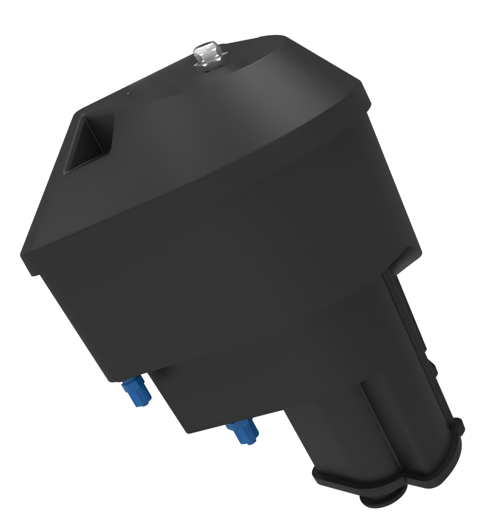
Close-up view of the Flow-Through Turbidity Meter flow cell and optical system

Core Components for Precise Measurement

The Flow Cell is the core component, providing a stable, controlled space for liquid flow. Made from corrosion-resistant glass or plastic with excellent optical properties, it ensures uniform flow without turbulence for maximum accuracy.

The high-precision Optical System utilizes stable LEDs or laser sources and sensitive photodetectors to capture scattered light signals. The Signal Processing Unit then converts these signals into intuitive turbidity values displayed on a clear screen.

Detailed Product Structure and Operation
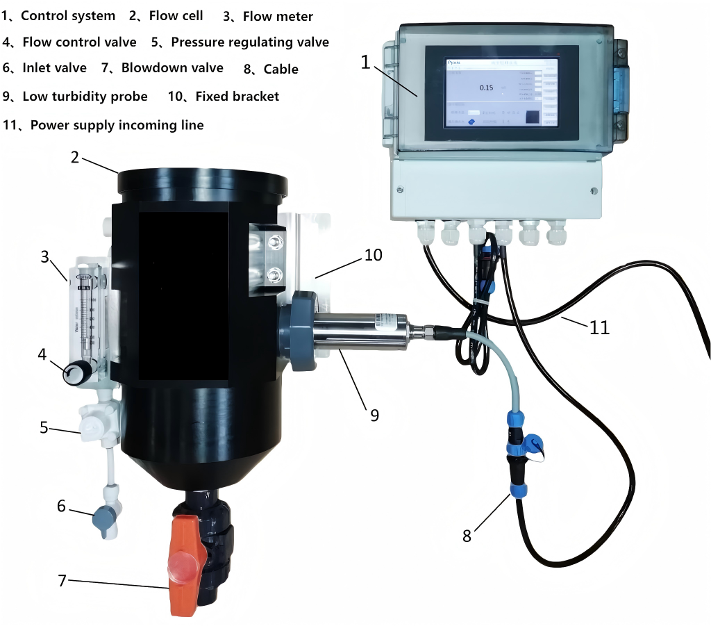
Diagram of Flow-Through Turbidity Meter system connections and flow control

Integrated Flow Control and Connectivity

A dedicated Flow Control System, comprising a flow meter and control valve, ensures a stable flow rate through the measurement chamber, which is critical for repeatable and high-precision turbidity measurement results.

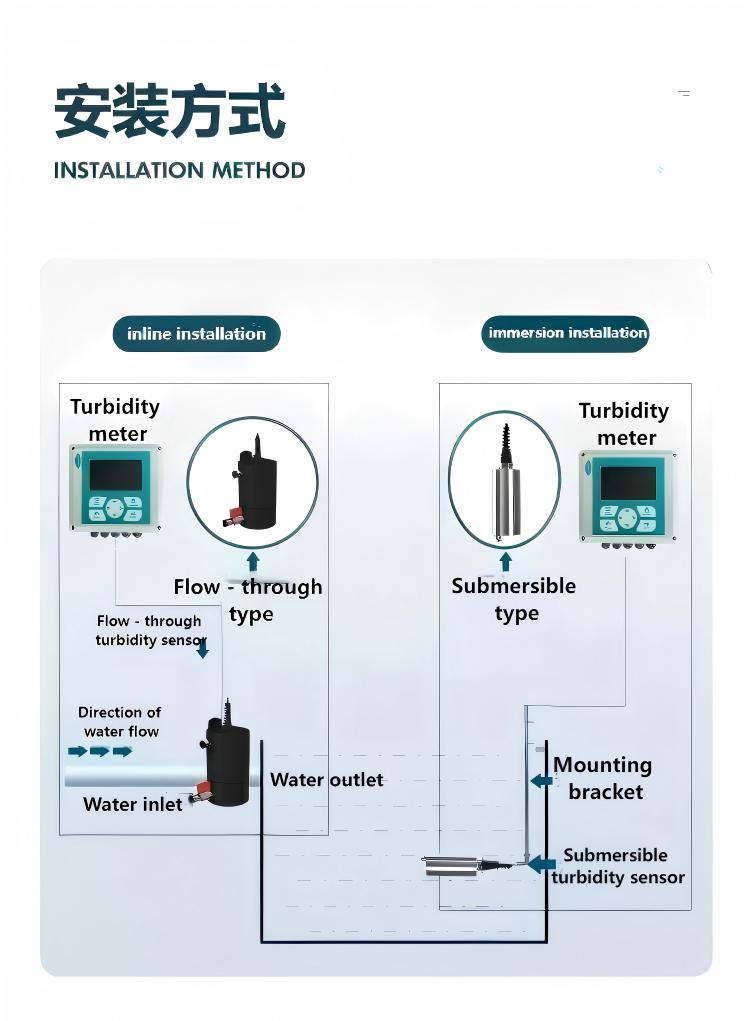
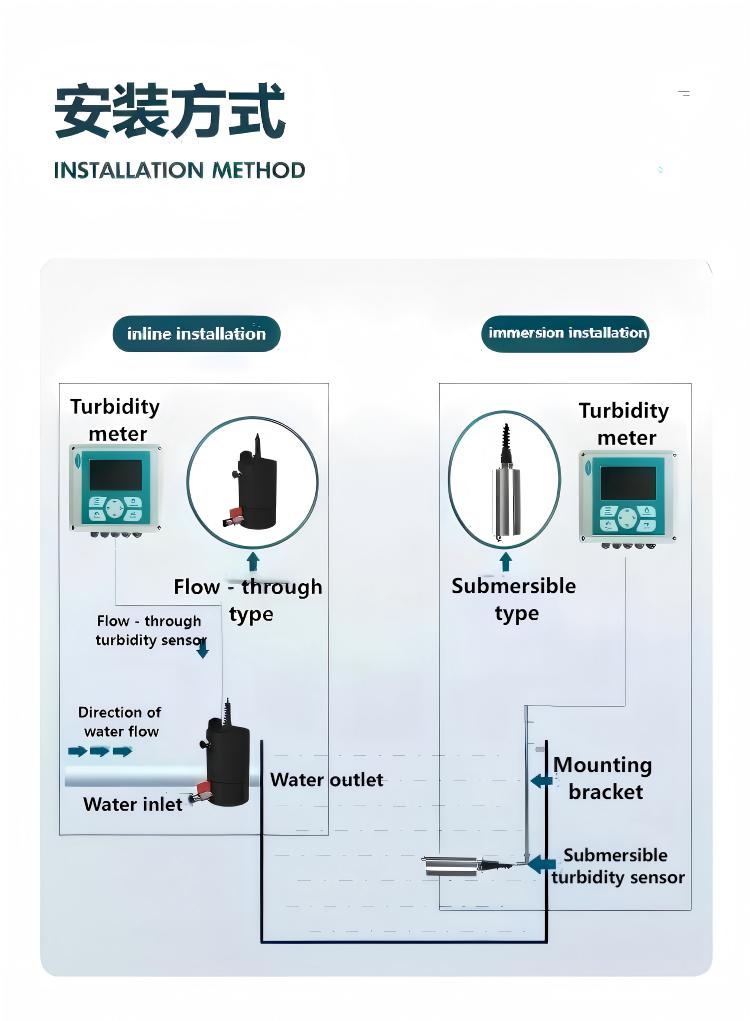
The inlet and outlet use quick-connect or threaded fittings for fast, leak-proof connection to external pipelines. The sturdy enclosure and versatile mounting bracket allow for flexible installation on walls, benches, or directly on pipelines.

Primary Application Fields for Water Quality Monitoring
Flow-Through Turbidity Meter applications in water and wastewater treatment plants

Drinking Water and Wastewater Treatment

In drinking water treatment plants, this meter provides real-time turbidity monitoring from raw water to finished water, ensuring compliance with safety standards. For wastewater treatment applications, it helps operators monitor influent and effluent to optimize process parameters and ensure compliant discharge.
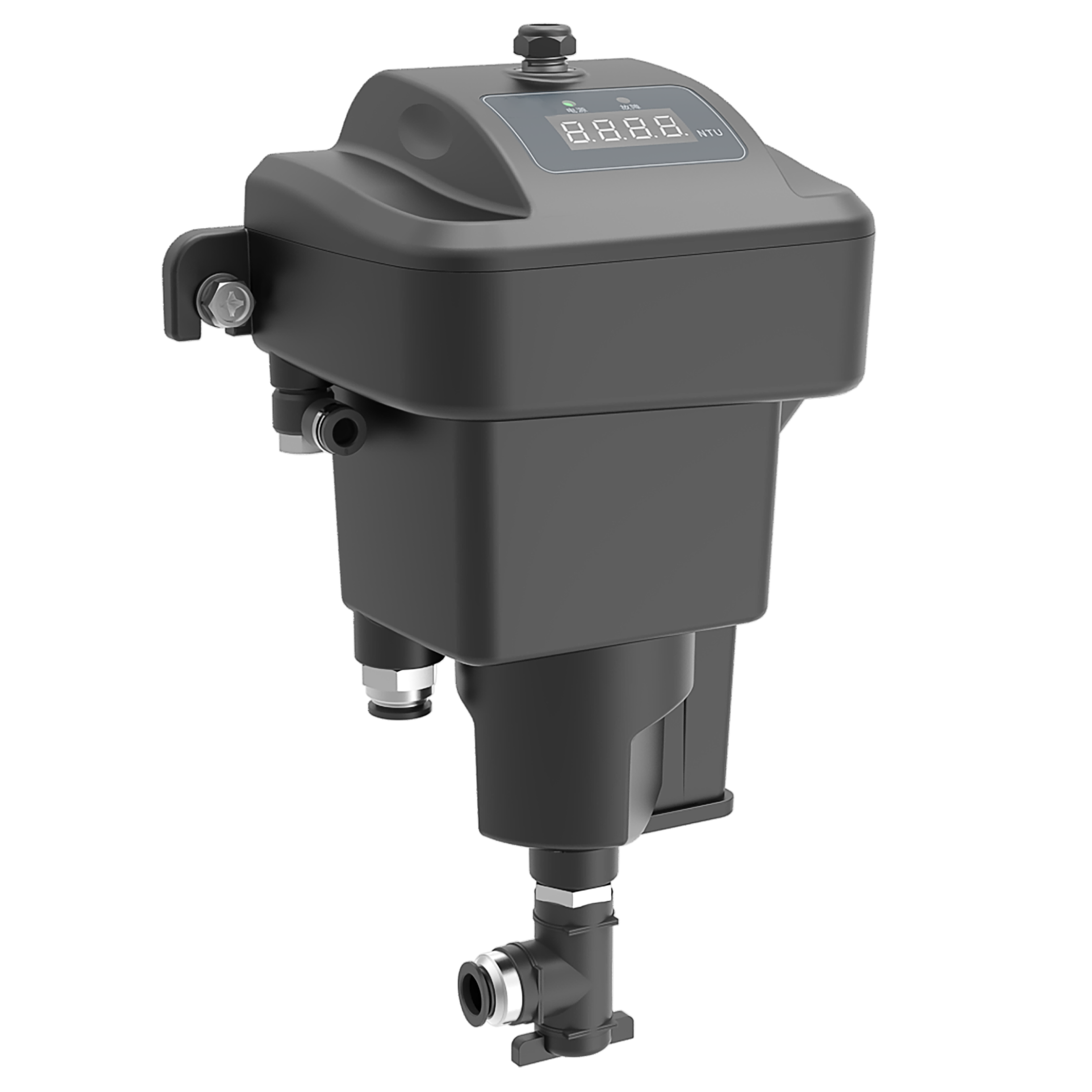
Flow-Through Turbidity Meter used in industrial process control and environmental monitoring

Industrial and Environmental Monitoring

The instrument is vital for industrial process control in chemical, pharmaceutical, and food & beverage production, where it monitors process water turbidity to guarantee product quality. Its strong adaptability also makes it ideal for long-term environmental monitoring of rivers, lakes, and oceans, providing essential data for water resource protection.

Technical Specifications

Parameter Specification
Measurement Principle Optical Scattering
Accuracy Typical ±2% FS or ±0.3NTU
Resolution 0.01NTU (Low), 0.1NTU (High)
Repeatability Error ≤ 1%
Response Time 30 seconds - 2 minutes
Operating Temperature 0°C to 50°C (or wider range)
Operating Humidity ≤ 90% RH (non-condensing)
Output Interfaces Analog (4-20mA), Digital (RS485, USB)
Key Features Flow-Through Design, Data Logging, Alarm Function, Multi-Parameter Display, Chemical Resistance

Contact Us

Need a custom solution? Our engineers are ready to help you design the perfect system.

Get In Touch
Downloads

User Manual for Circulating Turbidity Meter.pdf
PDF • 3381.8 KB

Related Questions

View All
What is RTU Remote Terminal Unit? How does RTU work in water monitoring systems?
View Answer
<p><strong>RTU (Remote Terminal Unit)</strong> is a microprocessor-controlled electronic device that serves as the critical interface between physical field equipment and centralized SCADA (Supervisory Control and Data Acquisition) or telemetry systems. In water monitoring systems, an RTU collects real-time data from field sensors—including flow meters, pressure transmitters, water level gauges, and water quality analyzers—and transmits this information to a central control center via wireless or wired communication networks.</p> <p><strong>How RTU Works in Water Monitoring Systems:</strong></p> <ul> <li><strong>Data Acquisition</strong>: The RTU continuously polls connected sensors through multiple I/O interfaces including analog inputs (4–20mA, 0–10V), digital inputs (pulse, status), and serial communication ports (RS-232/RS-485). For water monitoring, typical sensor inputs include flow rate from electromagnetic or ultrasonic flowmeters, water level from radar or submersible level sensors, pressure from transmitters, and water quality parameters such as pH, turbidity, and dissolved oxygen.</li> <li><strong>Signal Processing & Logging</strong>: Raw sensor signals are filtered, linearized, and converted to engineering units. The RTU performs local data logging with time-stamped records stored in non-volatile memory, ensuring zero data loss during communication outages. Typical storage capacity supports 10,000+ records with configurable logging intervals from 1 second to 24 hours.</li> <li><strong>Communication & Telemetry</strong>: RTUs support multiple communication protocols and transport layers. At the field level, <strong>Modbus RTU</strong> (over RS-485) is the most widely adopted protocol for sensor integration, while <strong>Modbus TCP</strong> enables Ethernet-based networking. For long-range telemetry, modern RTUs integrate multi-mode wireless options including <strong>4G LTE, NB-IoT, LoRa/LoRaWAN</strong>, and satellite communication, allowing deployments in remote watersheds, mountain reservoirs, and underground monitoring wells where traditional wired infrastructure is unavailable.</li> <li><strong>Control & Automation</strong>: Beyond data collection, RTUs execute local control logic—triggering alarms when water levels exceed thresholds, automatically starting or stopping pumps based on tank levels, controlling valve positions for flow regulation, and implementing PID control loops for pressure management in water distribution networks.</li> <li><strong>Power Management</strong>: For remote sites without grid power, RTUs feature ultra-low-power designs with sleep-mode current consumption as low as 50μA, enabling months of autonomous operation on battery power supplemented by small solar panels (typically 10–50W). Advanced power scheduling wakes the RTU on configurable intervals or upon sensor-triggered events.</li> </ul> <p><strong>RTU vs PLC — Key Differences:</strong></p> <p>While both RTUs and PLCs (Programmable Logic Controllers) perform industrial control functions, they are optimized for different deployment scenarios. RTUs are purpose-built for <strong>geographically distributed, remote, and environmentally harsh installations</strong> with emphasis on wide-area communication, ultra-low power consumption, and extended temperature ranges (-40°C to +70°C). PLCs excel in <strong>centralized factory-floor automation</strong> with high-speed deterministic control, extensive I/O density, and complex sequential logic. In water monitoring, RTUs are the preferred choice for river basin telemetry networks, reservoir monitoring stations, irrigation canal gate control, and urban drainage monitoring—applications where sites may be tens or hundreds of kilometers apart with limited power and no permanent communication infrastructure.</p> <p><strong>Typical Deployment Architecture:</strong></p> <p>A typical RTU-based water monitoring system follows a three-tier architecture. At the <strong>field layer</strong>, sensors (flowmeters, level gauges, rain gauges, water quality probes) connect to the RTU via wired interfaces within a monitoring station enclosure. The RTU aggregates and pre-processes data locally. At the <strong>communication layer</strong>, data is transmitted via 4G/NB-IoT/LoRa to a central data server or cloud IoT platform using protocols such as MQTT, HTTP, or the hydrological standard <strong>SL651-2014 / SZY206</strong>. At the <strong>application layer</strong>, SCADA software, water resource management platforms, and mobile dashboards visualize real-time and historical data, generate reports, and issue alarms—enabling water authorities to make informed operational decisions.</p> <p><strong>Ecolor Technology RTU Solutions:</strong></p> <p>Ecolor Technology's <strong>Hero V9 Series</strong> offers two primary RTU configurations for water monitoring applications:</p> <ul> <li><strong><a href="/EN/products/hero-v9-ec32-measurement-control-terminal">EC32 — Measurement and Control Terminal</a></strong>: A versatile industrial RTU with rich I/O interfaces, Modbus RTU/TCP support, 4G/LoRa/NB-IoT communication, and ultra-low-power design suitable for general water resource monitoring, pump station control, and irrigation automation. Features local data storage, remote firmware upgrade, and wide operating temperature range.</li> <li><strong><a href="/EN/products/hero-v9-ec60-data-acquisition-terminal">EC60 — Compact Data Acquisition Terminal</a></strong>: A cost-optimized, compact RTU designed for high-density sensor deployments with streamlined I/O, embedded 4G communication, and simplified installation—ideal for large-scale river monitoring networks and smart city drainage monitoring projects where cost per monitoring point is critical.</li> </ul> <p>Both models feature solar-ready power input, IP65+ environmental protection, and compatibility with Ecolor's cloud-based water monitoring platform for seamless data integration and visualization.</p>
How many sensors can one RTU handle simultaneously? What types of flow meters and level sensors are supported?
View Answer
<p>The <strong>EC32 RTU series</strong> supports up to 32 analog inputs and 16 digital inputs, while the <strong>EC60 RTU series</strong> can handle up to 60 mixed signal channels for large-scale monitoring stations. Supported sensor types include:</p><ul><li><strong>Electromagnetic flow meters</strong>: LGF series integral/remote types with 4-20mA or pulse signal inputs</li><li><strong>Ultrasonic flow meters</strong>: Clamp-on, inline, insertion, and ultrasonic water meter configurations</li><li><strong>Radar flow meters</strong>: HZ-KSLF multi-band Doppler radar for non-contact measurement</li><li><strong>Level sensors</strong>: Visualized radar level meters, ultrasonic level sensors, submersible pressure transducers</li><li><strong>Water quality sensors</strong>: pH, dissolved oxygen, turbidity, conductivity parameters</li></ul><p>The RTU features <strong>multi-protocol conversion</strong> capabilities, simultaneously handling Modbus, Hart, 4-20mA interfaces. Built-in intelligent algorithms provide data preprocessing, anomaly detection, and edge computing to optimize cloud data transmission efficiency for water treatment and industrial monitoring applications.</p>
How does groundwater monitoring network achieve multi-parameter real-time measurement and data transmission?
View Answer
<p><strong>Groundwater monitoring networks</strong> deploy distributed sensor stations to continuously measure water levels, quality parameters, and flow characteristics across aquifer systems. The comprehensive monitoring solution includes:</p><ul><li><strong>FMCW radar level sensors</strong>: Precise groundwater level measurement with 1mm resolution for long-term trend analysis</li><li><strong>EC32 RTU terminals</strong>: Solar-powered ultra-low power design for remote locations with 4G connectivity</li><li><strong>Ultrasonic flowmeters</strong>: Non-intrusive measurement of groundwater flow velocity and direction</li><li>Multi-parameter water quality probes: Real-time monitoring of pH, dissolved oxygen, turbidity, and conductivity</li></ul><p>The system utilizes <strong>4G communication technology</strong> for real-time data transmission to cloud-based platforms, enabling remote access to monitoring data, historical trends, and alarm notifications. Advanced analytics provide insights into aquifer behavior, seasonal variations, and pollution events. The <strong>multi-tier alarm system</strong> automatically alerts water managers when parameters exceed predetermined thresholds, supporting proactive groundwater resource management and environmental protection strategies.</p>
How to build a complete smart water infrastructure monitoring system? What core equipment and platforms are needed?
View Answer
<p>A complete smart water infrastructure monitoring system follows a four-layer architecture: Perception → Transmission → Platform → Application.</p><p><strong>1. Perception Layer:</strong> Electromagnetic flowmeters (pipe network flow), radar level meters (river/reservoir levels), Doppler radar flowmeters (open channel/drainage), pressure transmitters (pipe pressure), water quality sensors (pH/turbidity/DO).</p><p><strong>2. Transmission Layer:</strong> EC32/EC60 RTU series supporting 4G/NB-IoT/LoRa multi-mode communication, with built-in lithium battery + solar dual power supply.</p><p><strong>3. Platform Layer:</strong> Ecolor Cloud Platform (data aggregation, device management, GIS visualization, alarm linkage).</p><p><strong>4. Application Layer:</strong> DMA zone metering, pipeline leak analysis, flood early warning, water resource dispatch, carbon emission accounting.</p><p>CSSOC provides turnkey solutions from sensor to cloud, with typical deployment cycle of 2-4 weeks per project.</p>
What is Urban Lifeline Safety Engineering? Which sensors are needed for drainage, water supply, and gas pipeline monitoring?
View Answer
<p>Urban Lifeline Safety Engineering is the systematic real-time monitoring and intelligent early warning of critical urban infrastructure — water supply, drainage, gas, heating, and bridges — to prevent public safety incidents.</p><p><strong>Drainage Monitoring:</strong> Radar level meters (manhole water level) + Doppler radar flowmeters (pipe velocity/flow) + rain gauges (precipitation), with EC32 RTU for real-time urban flood warning and CSO (Combined Sewer Overflow) monitoring.</p><p><strong>Water Supply Monitoring:</strong> Electromagnetic flowmeters (DMA zoning) + pressure transmitters (network pressure) + online water quality analyzers (residual chlorine/turbidity/pH) for leak localization and water quality assurance.</p><p><strong>Gas Pipeline Monitoring:</strong> Pressure transmitters + gas leak detectors + intelligent cathodic protection monitoring via explosion-proof RTU terminals.</p><p>CSSOC focuses on the "water" component of urban lifelines, providing end-to-end solutions from sensor to cloud, with 120+ monitoring points deployed across multiple cities in China.</p>
What are the differences between Doppler radar flowmeter and electromagnetic or ultrasonic flowmeters?
View Answer
<p><strong>Doppler radar flowmeters</strong> offer distinct advantages over traditional flow measurement technologies. Compared to LGF series <strong>electromagnetic flowmeters</strong>, radar flowmeters provide non-contact measurement, eliminating pipeline installation requirements and maintenance issues, especially beneficial for large diameter open channel applications.</p><p>Key differences from <strong>ultrasonic flowmeters</strong> include:</p><ul><li>Measurement method: Radar uses microwave non-contact measurement, while ultrasonic requires contact or proximity to the medium</li><li>Environmental adaptability: Radar is unaffected by water turbidity, ultrasonic is sensitive to particle interference</li><li>Installation convenience: Radar mounts above channels, ultrasonic requires pipe penetration or clamp-on installation</li><li>Measurement range: Radar excels in high-flow open channels, ultrasonic better suited for pipe flow</li><li>Maintenance cost: Radar requires virtually no maintenance, ultrasonic sensors need regular cleaning</li></ul><p>The HZ-KSLF <strong>multi-band radar flowmeter</strong> is ideal for wastewater treatment plants, irrigation channels, and river monitoring, with EC32/EC60 RTU series enabling remote monitoring capabilities.</p>