Home / Products / Hydrological Intelligent Monitoring and Control Terminal (Hero V9 Series - EC32)
Back to Products
Hydrological Intelligent Monitoring and Control Terminal (Hero V9 Series - EC32)
Remote Terminal Units (RTU)

Hydrological Intelligent Monitoring and Control Terminal (Hero V9 Series - EC32)

The Hydrological Intelligent Monitoring and Control Terminal (Hero V9 Series - EC32), independently developed and produced by Ecolor Technology, featu...

Key Features

Type inspection passed per SL180-2015 "Telemetry Terminal for Hydrological Automatic Reporting System Equipment"
Compliant with "SZY206-2016 Water Resources Monitoring Data Transmission Protocol" and "SL651-2014 Hydrological Monitoring Data Communication Protocol"
Reliability verified with MTBF ≥ 50,000 hours, featuring remote firmware update capability
Supports remote PC and on-site manual configuration of various operation modes and parameters, with real-time clock auto-calibration and time adjustment
Can connect to multiple sensors including water level gauges, rain gauges, flow meters, etc.
Supports multiple communication methods: 4G, GPRS, Beidou Satellite, etc.

Key Features

Type inspection passed per SL180-2015 "Telemetry Terminal for Hydrological Automatic Reporting System Equipment"
Compliant with "SZY206-2016 Water Resources Monitoring Data Transmission Protocol" and "SL651-2014 Hydrological Monitoring Data Communication Protocol"
Explosion-proof certification (Explosion-proof rating: T6)
Reliability verified with MTBF ≥ 50,000 hours, featuring remote firmware update capability
Automatic data reporting
Supports remote PC and on-site manual configuration of various operation modes and parameters, with real-time clock auto-calibration and time adjustment
Can connect to multiple sensors including water level gauges, rain gauges, flow meters, etc.
Supports multiple communication methods: 4G, GPRS, Beidou Satellite, etc.
Intuitive LCD display for real-time presentation of key hydrological data and device status
Supports expansion of relay pulse analog interface functions to meet diverse control needs

Hydrological Intelligent Monitoring and Control Terminal (Hero V9 Series - EC32)

The Hydrological Intelligent Monitoring and Control Terminal (Hero V9 Series - EC32) is a core device for modern hydrological monitoring systems, integrating remote data acquisition, precise control, and efficient communication. Developed by Ecolor Technology, it ensures the stable and efficient operation of hydrological monitoring and control systems by responding in real-time to host computer instructions and driving end actuators.

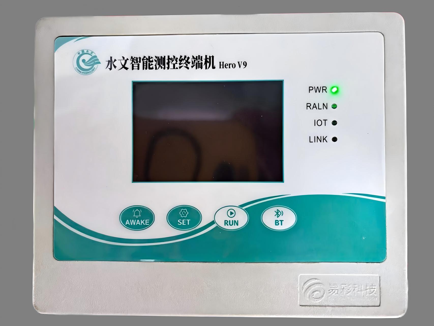
Hero V9 Series EC32 Hydrological Monitoring Terminal front view

Real-Time Data Display and Intuitive Interface

The terminal's LCD screen presents key hydrological acquisition data such as water level and flow rate in real-time through an intuitive human-machine interface. It also clearly displays operational information like device working mode and communication status, providing operators with immediate system visibility.

Broad Sensor Compatibility and System Expandability

For diverse monitoring needs, the EC32 terminal can easily connect externally to various professional hydrological monitoring instruments and sensors. It supports high-precision rain gauges, sensitive water level gauges, and flow meters, solidifying the hardware foundation for a comprehensive hydrological monitoring system.

Core Features & Technical Specifications

Standards & Compliance

Type inspection passed per SL180-2015. Compliant with SZY206-2016 and SL651-2014 hydrological data protocols, ensuring standardized and compatible data transmission.

Reliability & Durability

Features an MTBF ≥ 50,000 hours and holds an explosion-proof certification (Rating: T6). Includes remote firmware update capability for sustained performance.

Communication & Connectivity

Supports multiple communication methods including 4G, GPRS, and Beidou Satellite. Allows connection to various sensors and supports relay pulse analog interface expansion.

Key Operational Parameters

Feature Description
Data Reporting Automatic data reporting with support for remote PC and on-site manual configuration.
Time Management Real-time clock auto-calibration and time adjustment functionality.
Protocol Support Adheres to SZY206-2016 Water Resource Monitoring Data Transmission Protocol and SL651-2014 Hydrological Monitoring Data Communication Protocol.
Control Expansion Supports expansion of relay pulse analog interface functions to meet diverse control needs.
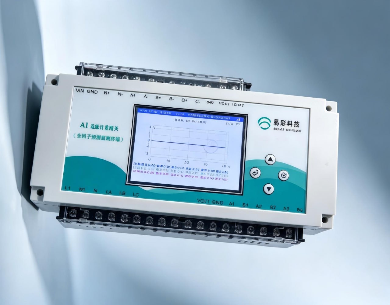
EC32 Terminal installation and sensor connectivity diagram

Seamless Integration into Hydrological Networks

By strictly adhering to industry-standard hydrological monitoring data communication protocols, the Hero V9 Series EC32 ensures standardized and accurate data transmission. This allows for seamless integration into existing hydrological monitoring networks, promoting industry-wide standardization and interoperability.

Advanced Command and Control System

The terminal's advanced command interaction system can respond in real-time and accurately execute instructions from the host computer. This precise control is fundamental for driving end actuators and managing complex hydrological monitoring and control system operations.

Applications in Hydrological Monitoring and Control

Flash Flood Warning Systems

Provides real-time monitoring of critical parameters like rainfall and water level, delivering essential data for early flash flood warnings and risk management.

Reservoir Operation Monitoring

Ensures efficient operation and scheduling in reservoir monitoring systems by delivering accurate data on water levels and inflow/outflow rates.

Dam Seepage and Safety Monitoring

Plays a vital role in dam seepage monitoring by precisely detecting potential hazards and changes in seepage pressure, contributing to structural safety.

As a core device in the field of intelligent hydrological monitoring, the Hero V9 EC32 terminal strongly promotes the rational development, utilization, and protection of water resources. It provides crucial technical support for the steady development of modern hydrological endeavors and water resource management.

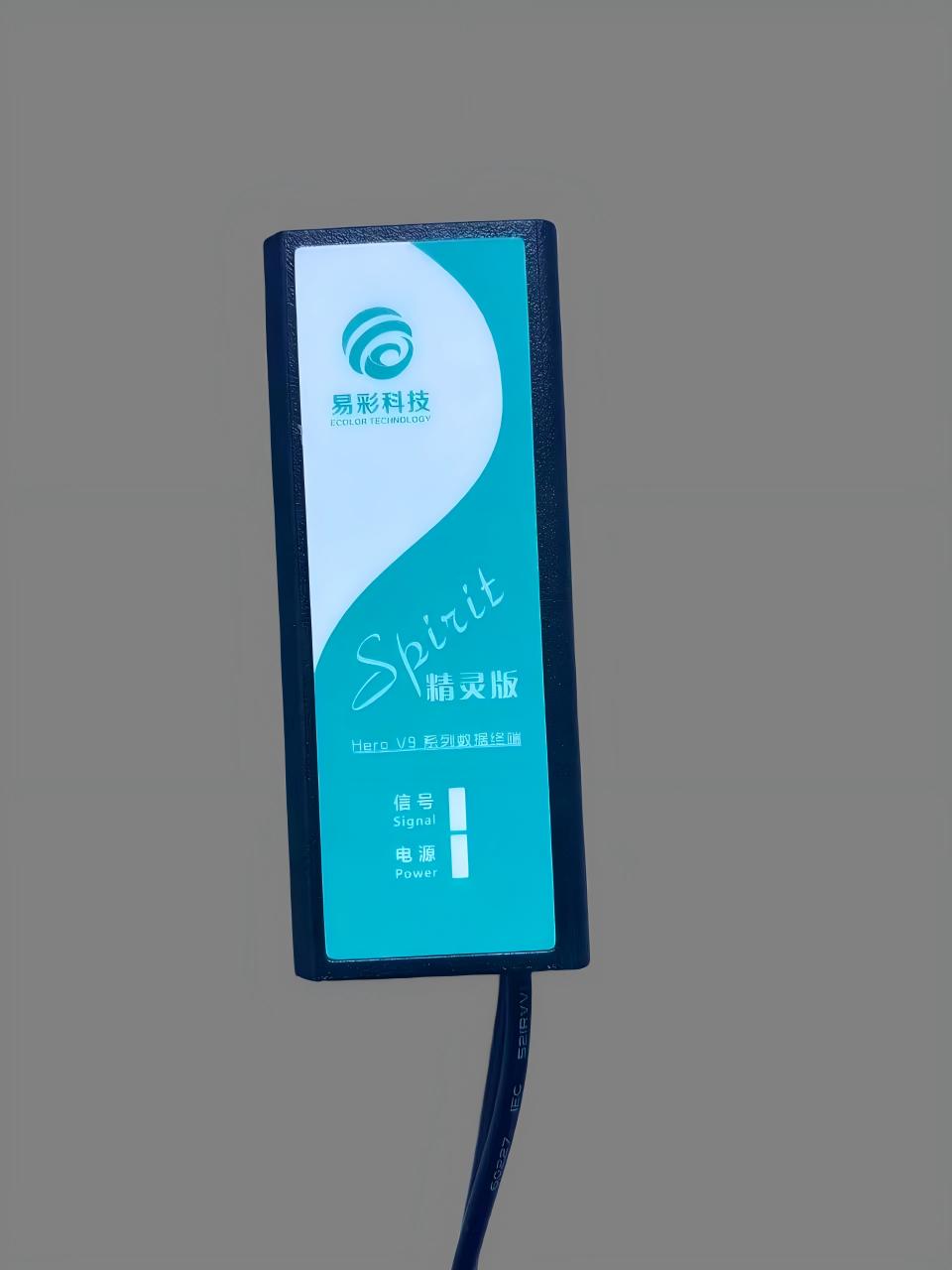
Hero V9 EC32 Terminal internal board and components Hydrological Monitoring Terminal rugged enclosure and ports
Hero V9 Series EC32 system deployment in field application

Contact Us

Need a custom solution? Our engineers are ready to help you design the perfect system.

Get In Touch
Downloads

Hydrological Intelligent Monitoring and Control Terminal (Hero V9 series - EC32).pdf
PDF • 1076.3 KB

Related Questions

View All
How does 4G data transmission work in Doppler radar flowmeters? What communication protocols are supported?
View Answer
<p><strong>Doppler radar flowmeter 4G data transmission</strong> is implemented through EC32/EC60 RTU series, supporting full-network 4G-LTE connectivity with built-in high-gain antennas for stable signal reception. The <strong>4G remote data transmission</strong> employs multiple encryption technologies to ensure secure and reliable data delivery.</p><ul><li>Communication protocols: Modbus RTU/TCP, MQTT, HTTP, TCP/UDP</li><li>Data formats: JSON, XML, custom protocols</li><li>Transmission frequency: Real-time/scheduled reporting, 1 minute-24 hours configurable</li><li>Network compatibility: Full-network 4G (GSM/CDMA/LTE carriers)</li><li>Remote configuration: SMS/platform remote parameter setting</li><li>Auto-reconnection: Automatic reconnection mechanism prevents data loss</li></ul><p>The system integrates seamlessly with water management platforms, SCADA systems, and IoT cloud platforms. Combined with <strong>radar flow monitoring</strong> equipment, it creates comprehensive smart water solutions for real-time flow data collection, transmission, storage, and analytics in municipal and industrial applications.</p>
How does the velocity-area method work in Doppler radar flowmeters for accurate flow measurement?
View Answer
<p><strong>Doppler radar flowmeters</strong> employ the velocity-area method to achieve non-contact, non-intrusive flow measurement in open channels, rivers, and partially filled pipes. This methodology separates flow computation into two independent measurements—surface velocity and cross-sectional area—and then combines them to derive volumetric flow rate, eliminating the need for in-water structures like weirs or flumes while avoiding sensor fouling from debris, sediment, or biological growth.</p> <p><strong>The Velocity-Area Method — Step by Step:</strong></p> <ol> <li><strong>Surface Velocity Measurement via Doppler Effect</strong>: The radar flowmeter transmits a continuous microwave signal (typically in the K-band at 24.125 GHz or W-band at 77 GHz) at a known frequency toward the water surface at an incidence angle (commonly 30°–60° from vertical). The transmitted signal reflects off surface disturbances—ripples, waves, floating debris, or turbulent eddies—that act as moving scatterers. Due to the Doppler effect, the frequency of the reflected signal is shifted in proportion to the velocity of these surface scatterers. The frequency shift Δf is given by the Doppler equation: <strong>Δf = 2 × v × cos(θ) × f₀ / c</strong>, where v is the surface velocity, θ is the incidence angle relative to the flow direction, f₀ is the transmitted frequency, and c is the speed of light. The radar receiver demodulates the returned signal and extracts velocity using Fast Fourier Transform (FFT) spectral analysis, typically achieving velocity resolution of ±0.01 m/s.</li> <li><strong>Cross-Sectional Area Determination</strong>: Simultaneously, an integrated non-contact level sensor—typically an ultrasonic or radar level gauge—measures the water level (stage height) from the same mounting position above the channel. The wetted cross-sectional area A is then computed using pre-configured channel geometry parameters. For a <strong>rectangular channel</strong>: A = W × H (width × water depth). For a <strong>trapezoidal channel</strong>: A = (B + m × H) × H, where B is the bottom width and m is the side slope ratio. For <strong>circular pipes</strong> (partially filled): A = (D²/8) × (θ − sin θ), where D is the pipe diameter and θ is the central angle subtended by the water surface, calculated from the fill depth ratio. For <strong>natural river cross-sections</strong>, a lookup table or polynomial model derived from bathymetric survey data is used to map stage height to cross-sectional area.</li> <li><strong>Flow Rate Computation</strong>: Volumetric flow rate Q is calculated using the velocity-area formula: <strong>Q = K × V<sub>surface</sub> × A</strong>, where K is the <strong>velocity correction coefficient</strong> (also called the velocity index or surface-to-mean velocity ratio). The coefficient K accounts for the fact that radar measures surface velocity, while the mean cross-sectional velocity—which determines actual volumetric flow—depends on the full vertical velocity profile. For turbulent open-channel flow with a logarithmic or power-law velocity distribution, K typically ranges from <strong>0.85 to 0.95</strong>, with the exact value determined by channel roughness (Manning's n), hydraulic radius, and water surface slope. Modern Doppler radar flowmeters include built-in hydraulic models that dynamically adjust K based on real-time stage and velocity measurements for improved accuracy.</li> </ol> <p><strong>Factors Affecting Measurement Accuracy:</strong></p> <ul> <li><strong>Cross-Section Shape and Stability</strong>: The accuracy of area calculation depends directly on how well the pre-configured geometry matches the actual channel. Erosion, sediment deposition, vegetation growth, or ice formation that alters the cross-section will introduce systematic errors. Regular bathymetric re-surveys and geometry recalibration are recommended for natural channels, typically annually or after major flood events.</li> <li><strong>Velocity Distribution</strong>: The relationship between surface velocity and mean velocity (the K coefficient) assumes a well-developed turbulent velocity profile. Immediately downstream of hydraulic structures (weirs, gates, sharp bends, confluences), flow separation and secondary currents create non-standard velocity distributions that invalidate the standard K factor. Maintain a minimum straight approach reach of 10–20 times the channel width upstream of the measurement section.</li> <li><strong>Surface Wave and Wind Effects</strong>: Strong winds can accelerate or decelerate the water surface layer independently of the bulk flow, introducing velocity bias. Wind-induced surface drift can shift K by ±5–10%. In exposed locations, wind shields or multiple measurement points with spatial averaging help mitigate this effect. Similarly, extremely smooth (glass-like) water surfaces with insufficient scattering targets can produce weak or intermittent Doppler returns—multi-band radar technology with adaptive frequency selection improves signal capture under these conditions.</li> <li><strong>Mounting Geometry</strong>: Errors in the incidence angle measurement or mounting height propagate into velocity calculations. A 1° angle error produces approximately a 1–2% velocity error depending on the nominal angle. Precision mounting brackets with inclinometers and automated angle compensation improve installation repeatability.</li> </ul> <p><strong>Comparison with Other Flow Measurement Methods:</strong></p> <ul> <li><strong>vs. Weirs and Flumes</strong>: Velocity-area radar requires no in-stream structure, eliminating head loss, upstream sediment accumulation, and maintenance of hydraulic structures. However, weirs/flumes provide higher accuracy (±2–3%) in small, controlled channels where permanent structures are acceptable.</li> <li><strong>vs. Acoustic Doppler Current Profilers (ADCP)</strong>: ADCPs measure velocity at multiple depths and compute a full velocity profile, achieving superior accuracy (±1–2%) in deep, wide rivers. However, ADCPs require submerged sensors prone to biofouling and debris damage, whereas radar's non-contact operation ensures minimal maintenance—ideal for flood-prone, high-sediment, or debris-laden waterways.</li> <li><strong>vs. Transit-Time Ultrasonic</strong>: Transit-time ultrasonic systems (cross-path or multi-path) provide high accuracy (±0.5–1%) in clean water with stable temperature, but performance degrades with entrained air, high suspended solids, or wide temperature swings. Radar is largely immune to these factors as it operates entirely above the water surface.</li> </ul> <p><strong>Ecolor Technology Doppler Radar Flowmeter Solution:</strong></p> <p>Ecolor Technology's <strong><a href="/EN/products/multi-band-doppler-radar-flowmeter">Multi-band Doppler Radar Flowmeter</a></strong> represents the state-of-the-art in non-contact open channel flow measurement:</p> <ul> <li><strong>Multi-Band Radar Technology</strong>: Simultaneously transmits across multiple frequency bands (24 GHz and 77 GHz) with intelligent signal fusion to maintain reliable velocity readings under challenging surface conditions—from wind-rippled surfaces to near-calm conditions that would cause single-frequency radars to lose lock.</li> <li><strong>Integrated Design</strong>: Combines radar velocity sensor, ultrasonic level sensor, and RTU/data logger in a single weatherproof enclosure with solar power compatibility, 4G/LoRa telemetry, and Modbus RTU/TCP output for seamless SCADA and IoT platform integration.</li> <li><strong>Performance Specifications</strong>: Velocity range 0.1–20 m/s with ±0.01 m/s resolution; flow measurement accuracy ±3–5% of reading depending on site calibration; operating range 0.5–35 m from water surface; IP68 environmental rating.</li> <li><strong>Applications</strong>: River discharge monitoring for flood warning systems, irrigation canal flow measurement for water allocation accounting, urban drainage and stormwater monitoring, and industrial effluent discharge compliance measurement.</li> </ul>
What is RTU Remote Terminal Unit? How does RTU work in water monitoring systems?
View Answer
<p><strong>RTU (Remote Terminal Unit)</strong> is a microprocessor-controlled electronic device that serves as the critical interface between physical field equipment and centralized SCADA (Supervisory Control and Data Acquisition) or telemetry systems. In water monitoring systems, an RTU collects real-time data from field sensors—including flow meters, pressure transmitters, water level gauges, and water quality analyzers—and transmits this information to a central control center via wireless or wired communication networks.</p> <p><strong>How RTU Works in Water Monitoring Systems:</strong></p> <ul> <li><strong>Data Acquisition</strong>: The RTU continuously polls connected sensors through multiple I/O interfaces including analog inputs (4–20mA, 0–10V), digital inputs (pulse, status), and serial communication ports (RS-232/RS-485). For water monitoring, typical sensor inputs include flow rate from electromagnetic or ultrasonic flowmeters, water level from radar or submersible level sensors, pressure from transmitters, and water quality parameters such as pH, turbidity, and dissolved oxygen.</li> <li><strong>Signal Processing & Logging</strong>: Raw sensor signals are filtered, linearized, and converted to engineering units. The RTU performs local data logging with time-stamped records stored in non-volatile memory, ensuring zero data loss during communication outages. Typical storage capacity supports 10,000+ records with configurable logging intervals from 1 second to 24 hours.</li> <li><strong>Communication & Telemetry</strong>: RTUs support multiple communication protocols and transport layers. At the field level, <strong>Modbus RTU</strong> (over RS-485) is the most widely adopted protocol for sensor integration, while <strong>Modbus TCP</strong> enables Ethernet-based networking. For long-range telemetry, modern RTUs integrate multi-mode wireless options including <strong>4G LTE, NB-IoT, LoRa/LoRaWAN</strong>, and satellite communication, allowing deployments in remote watersheds, mountain reservoirs, and underground monitoring wells where traditional wired infrastructure is unavailable.</li> <li><strong>Control & Automation</strong>: Beyond data collection, RTUs execute local control logic—triggering alarms when water levels exceed thresholds, automatically starting or stopping pumps based on tank levels, controlling valve positions for flow regulation, and implementing PID control loops for pressure management in water distribution networks.</li> <li><strong>Power Management</strong>: For remote sites without grid power, RTUs feature ultra-low-power designs with sleep-mode current consumption as low as 50μA, enabling months of autonomous operation on battery power supplemented by small solar panels (typically 10–50W). Advanced power scheduling wakes the RTU on configurable intervals or upon sensor-triggered events.</li> </ul> <p><strong>RTU vs PLC — Key Differences:</strong></p> <p>While both RTUs and PLCs (Programmable Logic Controllers) perform industrial control functions, they are optimized for different deployment scenarios. RTUs are purpose-built for <strong>geographically distributed, remote, and environmentally harsh installations</strong> with emphasis on wide-area communication, ultra-low power consumption, and extended temperature ranges (-40°C to +70°C). PLCs excel in <strong>centralized factory-floor automation</strong> with high-speed deterministic control, extensive I/O density, and complex sequential logic. In water monitoring, RTUs are the preferred choice for river basin telemetry networks, reservoir monitoring stations, irrigation canal gate control, and urban drainage monitoring—applications where sites may be tens or hundreds of kilometers apart with limited power and no permanent communication infrastructure.</p> <p><strong>Typical Deployment Architecture:</strong></p> <p>A typical RTU-based water monitoring system follows a three-tier architecture. At the <strong>field layer</strong>, sensors (flowmeters, level gauges, rain gauges, water quality probes) connect to the RTU via wired interfaces within a monitoring station enclosure. The RTU aggregates and pre-processes data locally. At the <strong>communication layer</strong>, data is transmitted via 4G/NB-IoT/LoRa to a central data server or cloud IoT platform using protocols such as MQTT, HTTP, or the hydrological standard <strong>SL651-2014 / SZY206</strong>. At the <strong>application layer</strong>, SCADA software, water resource management platforms, and mobile dashboards visualize real-time and historical data, generate reports, and issue alarms—enabling water authorities to make informed operational decisions.</p> <p><strong>Ecolor Technology RTU Solutions:</strong></p> <p>Ecolor Technology's <strong>Hero V9 Series</strong> offers two primary RTU configurations for water monitoring applications:</p> <ul> <li><strong><a href="/EN/products/hero-v9-ec32-measurement-control-terminal">EC32 — Measurement and Control Terminal</a></strong>: A versatile industrial RTU with rich I/O interfaces, Modbus RTU/TCP support, 4G/LoRa/NB-IoT communication, and ultra-low-power design suitable for general water resource monitoring, pump station control, and irrigation automation. Features local data storage, remote firmware upgrade, and wide operating temperature range.</li> <li><strong><a href="/EN/products/hero-v9-ec60-data-acquisition-terminal">EC60 — Compact Data Acquisition Terminal</a></strong>: A cost-optimized, compact RTU designed for high-density sensor deployments with streamlined I/O, embedded 4G communication, and simplified installation—ideal for large-scale river monitoring networks and smart city drainage monitoring projects where cost per monitoring point is critical.</li> </ul> <p>Both models feature solar-ready power input, IP65+ environmental protection, and compatibility with Ecolor's cloud-based water monitoring platform for seamless data integration and visualization.</p>
How does Doppler radar flowmeter integrate with SCADA systems? Which communication protocols are supported?
View Answer
<p><strong>Doppler radar flowmeters</strong> offer comprehensive <strong>SCADA system integration capabilities</strong> through standard industrial communication protocols for seamless connectivity with supervisory systems. The HZ-KSLF series provides multiple integration solutions:</p><ul><li><strong>Protocol support</strong>: Compatible with mainstream industrial protocols including Modbus RTU/TCP, HART, 4-20mA analog signals ensuring compatibility with various SCADA platforms</li><li><strong>RTU integration</strong>: Paired with EC32/EC60 remote terminal units supporting multi-sensor connectivity for regional monitoring network deployment</li><li><strong>Communication methods</strong>: Supports RS485 wired communication, 4G/NB-IoT wireless transmission, Ethernet TCP/IP and other connection options</li><li><strong>HMI software compatibility</strong>: Fully compatible with leading HMI/SCADA software including WinCC, Wonderware, Citect with standard device drivers</li><li><strong>Cloud platform integration</strong>: Supports IoT platforms like AWS IoT, Microsoft Azure, Alibaba Cloud for remote monitoring and data analytics</li></ul><p>The system provides OPC server interfaces supporting real-time data exchange and historical data queries, delivering professional automation solutions for water management, environmental monitoring, and industrial applications.</p>
What are the features of EC32 RTU series? Ecolor EC32 remote terminal specifications and advantages
View Answer
<p><strong>EC32 RTU series</strong> represents Ecolor Technology's latest generation remote terminal units, specifically engineered for water monitoring and industrial automation applications. This product line delivers exceptional technical advantages and innovative features for modern SCADA systems.</p><p><strong>Key features of EC32 RTU series</strong>:</p><ul><li><strong>Ultra-low power consumption</strong>: Static current <1mA, supports solar panel + lithium battery power systems</li><li><strong>Multiple communication options</strong>: Built-in 4G full-network module supporting GPRS/3G/4G/NB-IoT</li><li><strong>Comprehensive I/O configuration</strong>: 8-channel AI analog inputs, 4-channel DI digital inputs, 2-channel relay outputs</li><li><strong>Industrial-grade reliability</strong>: IP68 protection rating, operating temperature -40℃~+70℃</li><li><strong>Intelligent data management</strong>: Local storage for 100,000 records with offline data buffering</li><li><strong>Remote maintenance capabilities</strong>: Supports remote configuration, firmware updates, and diagnostic functions</li></ul><p><strong>EC32 RTU</strong> integrates seamlessly with LGF electromagnetic flow meters, HZ-KSLF radar flow meters, creating comprehensive water IoT monitoring solutions for global markets.</p>
What are the key features and applications of Ecolor EC60 Compact RTU Remote Terminal Unit?
View Answer
<p>The <strong>EC60 Compact RTU Remote Terminal Unit</strong> by Ecolor Technology represents cutting-edge innovation in industrial IoT data acquisition and transmission. This advanced RTU system delivers exceptional performance through:</p><ul><li><strong>Ultra-low Power Consumption</strong>: ARM Cortex-M4 core with standby current as low as 5μA, enabling solar-powered autonomous operation</li><li><strong>Multi-interface Compatibility</strong>: Supports RS485, 4-20mA, pulse, and digital I/O signals for seamless integration with electromagnetic flowmeters, radar level sensors, and various field instruments</li><li><strong>4G Cellular Connectivity</strong>: Built-in industrial-grade 4G modem ensuring reliable data transmission across multiple carrier networks</li><li><strong>Rugged Industrial Design</strong>: IP65 protection rating, operating temperature range -40°C to +85°C for harsh environmental conditions</li></ul><p>Widely deployed in water management systems, environmental monitoring networks, precision agriculture, and industrial automation applications requiring remote data collection and SCADA integration.</p>