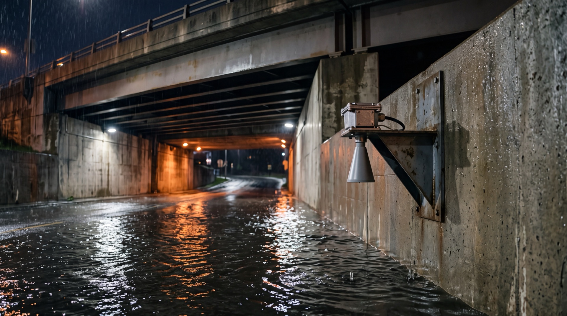
Radar Water Level Sensor Deployment for Urban Bridge Underpass Flood Warning
Urban road underpasses below bridges flood rapidly in heavy rain, and delayed warnings lead to vehicles driving into deep water. This solution deploys non-contact radar water level sensors with RTU telemetry and a cloud waterlogging platform to deliver real-time water level monitoring, graded alarms, on-site warning screens and coordinated traffic control for underpass flood prevention.
Overview
Summary
Urban road underpasses below bridges flood rapidly in heavy rain, and delayed warnings lead to vehicles driving into deep water. This solution deploys non-contact radar water level sensors with RTU telemetry and a cloud waterlogging platform to deliver real-time water level monitoring, graded alarms, on-site warning screens and coordinated traffic control for underpass flood prevention.
Key Advantages
Challenges
- Water rises several centimeters per minute; the warning window is only minutes and manual patrol cannot keep up
- Turbid floodwater with silt and debris buries and entangles contact-type sensors
- Most underpasses lack mains power; dense traffic leaves only short night construction windows
- Backend alarms alone are insufficient — entry screens and barriers must warn drivers directly
- Complete water level curves and alarm records are required for post-event review
Results
- Real-time automatic water level monitoring at second-level sampling with ≥99.9% data completeness
- Four-level alarms triggered within 1 minute, zero missed alarms during flood season
- On-site screens and barriers hard-linked, eliminating vehicles entering deep water
- Off-grid deployment completed in one night window, investment reduced by 70%+
- Full retention of water level curves and alarm records for review and retrofit decisions
Solution Details
Radar Water Level Sensor Deployment for Urban Bridge Underpass Flood Warning
In urban stormwater systems, underpasses beneath bridges, road undercrossings and railway box culverts are classic waterlogging risk points. During heavy rain, water rises fast and drains slowly — depth can grow from a few centimeters to over one meter within fifteen minutes. Traditional patrol-based warnings respond too late, and accidents of vehicles stalling or people being trapped in flooded underpasses recur across cities. Underpasses are confined spaces with dense traffic, limited lighting and complicated power conditions, demanding non-contact sensing that is easy to install and maintain. Non-contact radar water level sensors emit millimeter-wave radar pulses toward the water surface and compute level from propagation delay. With no parts touching the water and no in-water installation, they are naturally suited to underpasses — harsh environments with turbid water, debris and limited human access. Combined with low-power RTU telemetry and cloud-platform alarm linkage, they form a closed loop of real-time sensing, graded warning, on-site indication and coordinated response.
Core Challenges in Underpass Flood Monitoring
Water rises fast, warning window is extremely short: Large catchment areas and limited drainage mean underpass water levels can rise several centimeters per minute; only real-time automatic alerts can keep up.
Contact-type instruments do not fit: Floodwater carries silt and floating debris that bury or entangle submerged and float-type sensors; road-mounted equipment is crushed by traffic.
Installation and power conditions are harsh: Limited clearance, dense traffic and short construction windows; most underpasses have no mains power, requiring battery or solar supply and robustness against moisture, salt spray and vibration.
Warnings must reach both the site and managers: Backend alarms alone are not enough — entry warning screens, level indicator lights and barriers must activate to keep drivers out, while messages reach flood-control command.
Data must be traceable: Water level curves, alarm timestamps and response records must be retained for post-event review, liability determination and drainage retrofit planning.
Radar Water Level Sensor System Architecture
A four-layer architecture: non-contact sensing — edge telemetry — platform warning — on-site indication.
Non-contact sensing layer: Radar level sensors mount on sidewall or beam brackets, antenna beam pointing at the lowest point of the underpass. Millimeter waves penetrate rain and mist. Typical range 0.5–5 m covers the clearance, with millimeter-level resolution, temperature compensation and multi-echo interference rejection that filters waves caused by passing vehicles.
Edge telemetry layer: Sensors connect via RS485/Modbus to IP68 RTUs for filtering, threshold checking and reporting. Off-grid sites use lithium batteries (3+ years) or small solar float-charge. NB-IoT/4G Cat.1 links report at configurable intervals (down to 1 minute during storms), with local storage and back-fill on outage.
Platform warning layer: The urban waterlogging monitoring platform aggregates levels from all underpasses, executes four-level alarms (blue/yellow/orange/red) against preset thresholds, and pushes notifications to duty stations, SMS/App and city operations platforms, generating water level curves, statistics and daily reports.
On-site indication layer: Alarms drive entry LED warning screens and graded level indicator lights (green/yellow/red); red alarms can interlock with barriers and traffic signals to close the underpass. Warning state and water depth are displayed together so drivers can judge passability from a distance.
Measurement and Equipment Design for Underpass Radar Level Sensors
Beam angle and mounting geometry: Small beam angle (≤12°) avoids sidewall echo in narrow clearances; brackets avoid expansion joints and drip points, keeping the antenna above minimum measuring distance.
Interference handling: Vehicle wakes and pump starts disturb the surface; built-in echo quality evaluation and median filtering, with blind zones and averaging windows as needed, keep readings stable.
Protection and reliability: IP67 minimum, hydrophobic antenna cover, surge-protected power and communication interfaces, corrosion-treated brackets for damp saline environments.
Redundancy: Critical underpasses may use dual radars or radar + hydrostatic cross-check with automatic failover.
Deployment Essentials for Bridge Underpass Flood Warning
Site selection: Cover bridge lowest points, underpass entries and railway culverts first; at least one sensor per underpass, densified every 50–80 m for long ones.
Installation: Night-time lane-closure windows; chemical anchors into structural beams or sidewalls; antenna clearance above maximum water level; cables in conduit.
Threshold calibration: Four alarm levels set by clearance, safe fording depths (15 cm cars / 30 cm trucks) and drainage capacity; full alarm chain verified before flood season.
Linkage configuration: Alarm outputs tested against warning screens, barriers and traffic signals, with notification targets defined per level.
Typical Applications of Radar Water Level Monitoring
Urban flood command: Underpass data feeds the municipal flood command platform, linked with rainfall and pump station data for emergency dispatch.
Traffic control: Red alarms automatically close barriers and update traffic guidance screens, preventing vehicles from entering flooded sections.
Drainage assessment: Long-term water level records quantify drainage bottlenecks to guide pipe network retrofits and pump upgrades.
Insurance and review: Complete level records provide objective evidence for incident review and insurance claims.
Technical Advantages of Radar Water Level Sensor Deployment
Non-contact, low maintenance
No in-water parts — no silting, no entanglement
Millimeter-level real-time
Second-level sampling captures fast rises
All-weather reliability
Penetrates rain, mist and darkness
Off-grid rapid deployment
Battery/solar — one night window
Closed-loop warning
Hard-linked to screens and barriers
Open integration
HJ212, SL651 and standard APIs
Key Product Specifications
- Millimeter-wave radar non-contact level sensing, no in-water parts
- Configurable 0.5–5 m range, millimeter resolution
- Small beam angle + multi-echo rejection filters vehicle wake interference
- IP67 housing, hydrophobic antenna cover, corrosion-resistant brackets
- RTU telemetry: NB-IoT/4G, reporting down to 1 minute during storms
- Battery/solar powered, 3+ years runtime
- Four-level alarm linkage with LED screens, level lights and barriers
- HJ212/SL651 protocols and standard APIs
? Reference Sources
- Urban Waterlogging Monitoring Technical Specifications — Ministry of Housing and Urban-Rural Development
- Radar Level Measurement Standards for Open Channel and Flood Applications (IEC 60079 / ISO 20456)
- SL651-2014 Hydrology Telemetry Protocol & HJ212-2017 Environmental Monitoring Communication Standard
- Field Deployment Case Studies — Municipal Drainage and Flood Control Command Centers
Approach
How we implement intelligence into your infrastructure step by step.
Site survey and point selection
Check clearance, lowest points, power and network conditions; confirm sensor positions and bracket design.
Equipment selection and thresholds
Select range and beam angle by clearance; set four alarm levels by safe fording depths.
Night-time installation
Anchor brackets during lane closure; mount sensors and RTUs; route cabling in conduit.
Commissioning and linkage verification
Calibrate level accuracy; verify the full alarm chain and screen/barrier linkage.
Flood-season operation and review
Densify reporting during storms; produce post-season reports and assess drainage bottlenecks.
❓ Related FAQs
Related Solutions

Ready to Optimize Your Business?
Contact us, and our professional team will provide customized solutions to help your business achieve digital transformation.
Get In Touch