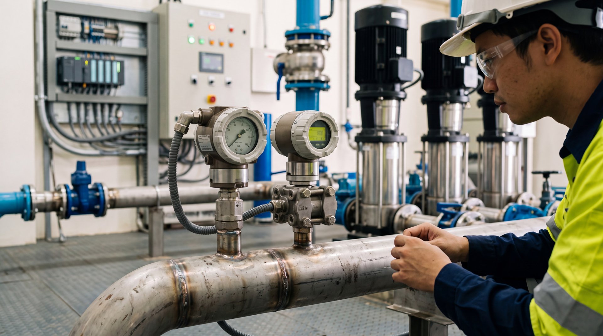
Pressure Transmitter Solution for Constant-Pressure Control in Secondary Water Supply Pump Rooms
Secondary water supply pump rooms often suffer from outlet pressure fluctuations, insufficient pressure for high-rise users at peak hours, and high energy consumption caused by crude pressure-switch control and frequent pump starts. This solution uses high-accuracy pressure transmitters with PLCs and variable-frequency drives to build a closed-loop constant-pressure water supply system, combined with a remote pump-room monitoring platform, delivering stable supply pressure, on-demand pump speed regulation, intelligent multi-pump switching and significant energy savings.
Overview
Summary
Secondary water supply pump rooms often suffer from outlet pressure fluctuations, insufficient pressure for high-rise users at peak hours, and high energy consumption caused by crude pressure-switch control and frequent pump starts. This solution uses high-accuracy pressure transmitters with PLCs and variable-frequency drives to build a closed-loop constant-pressure water supply system, combined with a remote pump-room monitoring platform, delivering stable supply pressure, on-demand pump speed regulation, intelligent multi-pump switching and significant energy savings.
Key Advantages
Challenges
- Demand swings several times between peaks and troughs; pressure must respond within seconds
- Pressure-switch differentials are wide and sluggish, causing frequent starts, water hammer and high energy use
- Parallel multi-pump add/remove switching causes pressure dips if mishandled
- Unmanned scattered rooms need instant remote alerts and full traceability
- Humid condensing environments challenge transmitter sealing and zero stability
Results
- Outlet pressure held within ±0.01 MPa of setpoint; peak-hour high-floor complaints eliminated
- Pumps run at demand-matched speed with 20-40% overall energy savings
- Start/stop cycles reduced by 90%+, water hammer and wear greatly reduced
- Dual-transmitter redundancy with break detection; single faults do not disturb control
- Pressure curves and alarms fully logged; unmanned anomalies handled within 5 minutes
Solution Details
Pressure Transmitter Solution for Constant-Pressure Control in Secondary Water Supply Pump Rooms
In urban water supply, the secondary supply pump room is the "last mile" connecting the municipal network to high-rise users. As variable-frequency constant-pressure technology matures, pump-room control is shifting from crude pressure-switch plus fixed-speed operation to closed-loop constant-pressure control built on pressure transmitters as the sensing core, PLCs as the control core, and VFDs as the actuators. The pressure transmitter measures outlet-header pressure in real time and converts it into a standard signal for the control system — it is the starting point of the entire closed loop, and its accuracy, response speed and long-term stability directly determine pressure quality and energy efficiency.
In practice, many aging pump rooms still rely on mechanical pressure switches or low-accuracy dial contacts: wide switching differentials and sluggish action cause frequent pump starts, water hammer, energy waste, poor pressure at peak hours for high floors, and excessive network pressure at night that worsens leakage. With pump rooms running unmanned, pressure anomalies and equipment faults are hard to detect in time. These problems demand a systematic upgrade in both retrofit and new-build projects.
Using diffused-silicon or ceramic-capacitive sensing elements, pressure transmitters convert medium pressure into electrical signals with 0.5-class or better accuracy. Combined with 4-20mA/HART output and PLC PID regulation, the system tracks demand changes within seconds and adjusts pump speed dynamically, holding supply pressure within ±0.01 MPa of the setpoint — precise matching of supply to demand.
Core Challenges in Secondary Water Supply Pressure Control
- Highly variable demand: Residential consumption swings several times between morning/evening peaks and night troughs; the pump room must respond within seconds, or high-floor users lose pressure.
- Crude pressure-switch control: Mechanical switches have 0.05-0.1 MPa differentials and delayed action; frequent starts cause water hammer, contactor wear and high energy use while pressure keeps fluctuating.
- Complex multi-pump switching: Rooms typically run 2-4 pumps in parallel with automatic add/remove logic; poorly handled switching causes pressure dips that users feel immediately.
- Reliability under unmanned operation: Scattered unmanned rooms require instant remote alerting for over-pressure, sensor faults and VFD alarms, with complete pressure logs for energy analysis and fault review.
- Humid, condensation-prone environment: Pump rooms are damp with large temperature swings; transmitters need moisture-proof sealing, vibration resistance and low long-term drift, otherwise distorted measurements mislead the controller.
System Architecture for Constant-Pressure Control
A four-layer design: precise sensing — closed-loop control — intelligent scheduling — remote monitoring.
Sensing layer: High-accuracy pressure transmitters are installed on the outlet header and at the most unfavorable network point. Range is selected at 1.2-1.5x pump head with 0.5% FS accuracy; 4-20mA signals feed PLC analog inputs. The header transmitter is the primary constant-pressure feedback; the remote-point transmitter validates pressure and compensates at peaks.
Control layer: PLC PID uses setpoint as target and header pressure as feedback to modulate the duty pump VFD frequency in real time. When one pump at full frequency cannot hold pressure, pumps are added automatically; when load falls, pumps are removed. Switching uses "start-before-stop with frequency preset" to suppress pressure dips.
Scheduling layer: Time-based pressure setpoints follow historical demand curves — automatic 2-5 m reduction at night cuts leakage and energy while guaranteeing end-point pressure; one-click fire/emergency high-pressure mode is supported.
Monitoring layer: RTU/gateways upload pressure, frequency, current, pump status and alarms via 4G/NB-IoT to the secondary supply platform, with mobile app and wallboard views and instant push alerts to maintenance staff.
Pressure Transmitter Selection and Installation Best Practices
Selection: Diffused-silicon element, 0.5% FS accuracy, 0-1.6 MPa range or customized to head; two-wire 4-20mA with HART for remote diagnostics; 316L stainless diaphragm resists chloride corrosion; IP65+ with anti-condensation vented cable.
Installation: Tap points sit on straight header pipe away from pump-outlet turbulence and check-valve water hammer; root valves and siphon bends allow online maintenance and shock buffering; sensors mount vertically upward to avoid liquid pooling; signal cables are shielded, grounded and routed away from VFD power lines.
Redundancy: Critical rooms deploy dual transmitters; the PLC compares both channels and alarms/switches on deviation beyond threshold, preventing single-sensor faults from causing false regulation.
Constant-Pressure Control Strategy with Pressure Transmitter Feedback
PID tuning: Step-disturbance tests at peak hours tune P/I parameters for fast response without overshoot, holding pressure within ±0.01 MPa.
Multi-pump logic: Add when frequency hits ceiling and pressure stays below setpoint for N seconds; remove when frequency drops below floor and pressure exceeds setpoint for N seconds — timers tuned to local demand swings.
Water-hammer protection: VFD ramp limits and PLC output clamps prevent abrupt frequency jumps; check valves combined with slow-closing valves eliminate stop hammer.
Remote Monitoring and O&M for Secondary Supply Pump Rooms
The platform shows real-time pressure curves, pump status, energy statistics and alarm logs; over-pressure, transmitter fault (4-20mA break detection) and VFD faults push tiered alerts; monthly energy and pressure-quality reports support retrofit evaluation and dispatch optimization.
Results Achieved with Pressure Transmitter-Based Closed-Loop Control
Retrofitted rooms typically hold outlet pressure within ±0.01 MPa of setpoint, eliminating peak-hour high-floor complaints; average pump speed drops with 20-40% energy savings; start/stop cycles fall by over 90%, greatly reducing water hammer and mechanical wear; unmanned anomalies are pushed and handled within 5 minutes, lifting both supply safety and O&M efficiency.
±0.01 MPa
Pressure Control Accuracy
20-40%
Energy Savings
90%+
Reduction in Start/Stop Cycles
≤2 s
Pressure Response Time
0.5% FS
Transmitter Accuracy
≤±0.1% FS/yr
Long-Term Stability
Key Technical Specifications
- Diffused-silicon element, 0.5% FS accuracy, long-term stability ≤±0.1% FS/year
- 0-1.6 MPa range customizable to pump head, 2x overpressure capability
- 4-20mA + HART output with remote configuration and diagnostics
- 316L diaphragm chloride-resistant, IP65 anti-condensation
- PLC PID closed loop, pressure response ≤2 s, overshoot-free tuning
- Intelligent multi-pump switching, start-before-stop suppresses dips
- Time-based setpoints with night pressure reduction for leakage and energy savings
- Secondary-supply platform integration via 4G/NB-IoT with tiered alarms
? Reference Sources
- GB/T 50054-2011 Code for Design of Low-Voltage Electrical Installations
- GB 50015-2019 Standard for Design of Building Water Supply and Drainage
- CJJ/T 154-2011 Technical Specification for Secondary Water Supply Engineering
- IEC 60770-1:2010 Transmitters for use in industrial-process control systems
Approach
How we implement intelligence into your infrastructure step by step.
Site survey and load assessment
Review pump head and flow, demand curves and worst-point pressure to set the constant-pressure target and transmitter range.
Device selection and tap-point design
Select transmitter accuracy and range, tap locations, and dual-redundancy installation plan.
Installation in shutdown window
Tap and weld root valves on the header, mount transmitters and impulse lines, route shielded cables to the PLC.
PID tuning and multi-pump commissioning
Step-test PID parameters and verify add/remove switching logic and water-hammer protection.
Grid integration and energy evaluation
Connect the remote platform and issue monthly pressure-quality and energy reports to refine dispatch.
❓ Related FAQs

Ready to Optimize Your Business?
Contact us, and our professional team will provide customized solutions to help your business achieve digital transformation.
Get In Touch