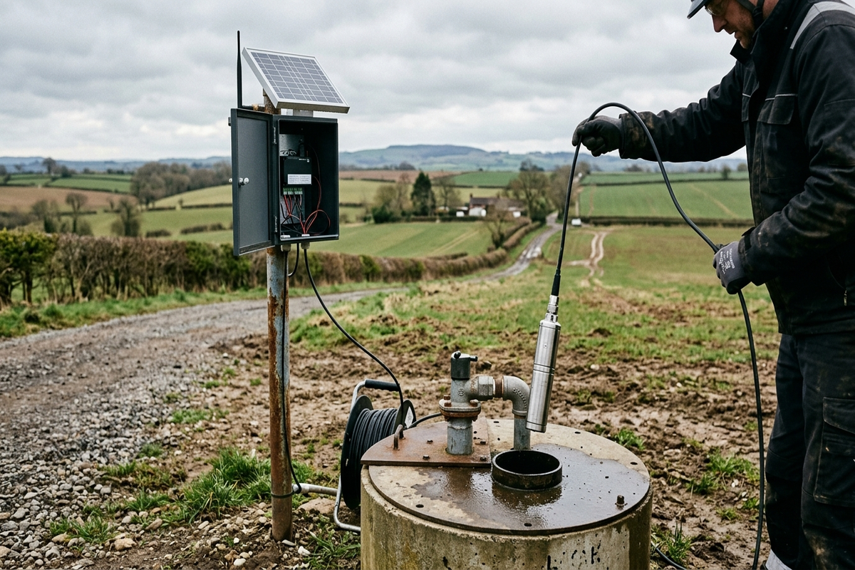
Submersible Level Transmitter Solution for Deep-Well Groundwater Dynamic Monitoring
Deep monitoring wells, wide water-level swings, remote off-grid locations and strict data-continuity requirements make manual groundwater observation impractical. This solution combines submersible level transmitters with low-power telemetry terminals and solar power to deliver continuous, automated monitoring of groundwater level and temperature, supporting over-extraction governance, water-resource tax metering and hydrogeological research.
Overview
Summary
Deep monitoring wells, wide water-level swings, remote off-grid locations and strict data-continuity requirements make manual groundwater observation impractical. This solution combines submersible level transmitters with low-power telemetry terminals and solar power to deliver continuous, automated monitoring of groundwater level and temperature, supporting over-extraction governance, water-resource tax metering and hydrogeological research.
Key Advantages
Challenges
- Great well depth and wide level swings demand full-range accuracy
- Remote off-grid sites require micropower solar self-sufficiency
- Thunderstorm/dust environments demand lightning and corrosion protection
- Data continuity directly affects over-extraction assessment and tax accounting
- Years of submersion cause zero drift and fouling that erode stability
Results
- Water-level error better than ±3 cm across 0–300 m deep wells
- Solar+battery power sustains 30+ days of continuous cloudy weather
- Half-day to one-day deployment per well without damaging well structure
- Synchronized level/temperature observation meeting monitoring standards
- Data completeness ≥99%, supporting over-extraction evaluation and water-tax metering
Solution Details
Submersible Level Transmitter Solution for Deep-Well Groundwater Dynamic Monitoring
Groundwater is a critical water supply in arid and semi-arid regions and a core object of water-resource management and ecological protection. As groundwater over-extraction control programs, water-resource tax pilots and national groundwater monitoring projects expand, demand for continuous groundwater observation is growing rapidly. Monitoring wells are typically tens to hundreds of meters deep and located far from the power grid. Manual measurement is labor-intensive, low-frequency and discontinuous — it cannot support the high-frequency data required for over-extraction assessment, ecological water-level early warning and abstraction regulation. The submersible level transmitter, based on hydrostatic pressure measurement, is suspended directly in the well and continuously converts water-column pressure into water level, providing a reliable automated means for deep-well groundwater dynamic monitoring.
Core Challenges in Deep-Well Groundwater Monitoring
Great depth and wide water-level swings: Monitoring wells are commonly 50–300 m deep with seasonal level fluctuations of tens of meters, demanding large range and consistent accuracy across the full measurement span.
Remote sites without grid power: Wells sit in farmland, mountains or desert areas where power is unavailable; equipment must run on microwatts and sustain itself on solar/battery power for years between services.
Harsh outdoor environments: Exposed to thunderstorms, dust, extreme temperatures and condensation, wellhead equipment needs lightning, water and corrosion protection while sensors endure permanent submersion.
Strict data continuity requirements: Groundwater trend analysis, over-extraction evaluation and water-tax accounting depend on long, gap-free time series — any data gap weakens trend judgment and settlement.
Long-term stability challenges: Years of submersion bring zero drift, membrane fouling and cable water ingress, which accumulate into measurement error; the device must offer long-term stability and on-site calibration.
Submersible Level Transmitter System Architecture
A four-layer architecture of "downhole sensing — wellhead acquisition — wireless telemetry — platform management":
Downhole sensing layer: A submersible level transmitter (piezoresistive/diffused-silicon) is suspended by armored stainless-steel cable to the design depth, measuring hydrostatic pressure at the probe and converting it to water level with atmospheric compensation; an integrated temperature sensor provides synchronized level/temperature observation.
Wellhead acquisition layer: A low-power RTU/hydrology terminal handles signal conditioning, data acquisition, barometric compensation and storage, supporting scheduled logging (e.g., hourly) and event reporting when level change exceeds a threshold.
Wireless telemetry layer: Data is uploaded via NB-IoT/4G/LoRa; in areas without cellular coverage, BeiDou short messages or satellite IoT fill the gap to keep data flowing.
Platform management layer: The groundwater monitoring platform renders hydrographs, groundwater-contour maps, fluctuation statistics, over-extraction assessment, limit-exceeding alarms and reports, and can exchange data with provincial/national groundwater platforms.
Key Deployment Points for Deep-Well Submersible Level Transmitters
Range and accuracy selection: Choose the range (0–100/200/300 m) by well depth and maximum water level burial; prefer 0.1%FS-class accuracy so water-level error stays at centimeter level across the full span.
Atmospheric compensation: Use vented-cable transmitters whose built-in vent tube feeds atmospheric pressure to the sensor back side, removing barometric effects; where venting is impossible, apply platform-side barometric correction.
Suspension installation: Suspend the sensor 0.5–1 m below the lowest dynamic water level; fix the cable at the wellhead with a flange or bracket and keep it clear of wall friction; add a sand shield in sandy wells.
Lightning and environmental protection: Install power and signal surge protectors in the wellhead cabinet (IP65+ with anti-condensation treatment); tilt the solar panel to local latitude and leave room for snow removal.
Power design: Solar panel plus LiFePO4 battery sized for 15–30 days of continuous cloudy weather; the RTU runs in sleep-wake micropower mode with milliwatt-level static consumption.
Typical Application Modes for Groundwater Level Monitoring
Groundwater monitoring networks: Regional well networks generating monthly/daily hydrographs and contour maps to track recharge-runoff-discharge dynamics.
Over-extraction governance evaluation: Paired wells in extraction and recharge zones quantify water-level recovery from cutback, source substitution and artificial recharge measures.
Water-resource tax metering: Online abstraction metering for irrigation and industrial wells provides the billing basis for water-resource tax collection.
Ecological water-level early warning: Threshold-based alarms in river-recharge zones and wetland reserves support ecological water dispatch.
Mine dewatering and salinization monitoring: Track the influence radius of mine dewatering on nearby domestic wells, and the link between irrigation-zone water tables and soil salinization.
Technical Advantages of the Submersible Level Transmitter
0.1%FS Accuracy
±3 cm error across 0–300 m
316L SS + Ceramic
Corrosion-resistant body
≤0.1%FS Drift/Year
Long-term stability
<1 mW Sleep
Micropower endurance
Dual Parameter
Level + temperature
Multi-Telemetry
NB-IoT/4G/LoRa/BeiDou
Full-range high accuracy: Diffused-silicon piezoresistive sensing with 0.1%FS accuracy options; water-level error better than ±3 cm across 0–300 m.
Long-term reliability: 316L stainless steel body and ceramic membrane resist corrosion; annual zero drift ≤0.1%FS with on-site zero calibration.
Dual level/temperature parameters: Integrated temperature measurement meets groundwater monitoring specifications for synchronized observation.
Micropower endurance: Sleep current <1 mW; solar+battery sustains 30+ days of cloudy weather and ≥1 year of maintenance-free operation.
Flexible telemetry: NB-IoT/4G/LoRa/BeiDou options with SL651 hydrological protocol support for platform integration.
Easy installation and maintenance: Wellhead suspension installation completed in half a day to one day per well; the sensor can be lifted out for service without affecting the well structure.
Typical Application Scenarios for Deep-Well Monitoring
- Automation retrofit of national and provincial groundwater monitoring well networks
- Dynamic monitoring in groundwater over-extraction governance zones
- Abstraction metering for irrigation wells and water-resource tax collection
- Online ecological water-level early warning in river-lake recharge areas
- Monitoring of mine dewatering impact on surrounding water levels
- Dynamic monitoring of seawater intrusion interfaces in coastal zones
- Ecological groundwater-level monitoring in wetland reserves
Deployment Recommendations for Submersible Level Transmitter Installation
- Well survey and site selection: Collect well depth, casing diameter, static level and historical fluctuation data; verify well integrity on site; define monitoring depth and installation plan.
- Device selection and range configuration: Choose the range by maximum water-level burial plus safety margin; define accuracy class, communication and power configuration per well.
- Suspension installation and wellhead fixing: Suspend the sensor to design depth, fix the wellhead bracket and acquisition cabinet, and complete vent-cable routing and lightning grounding.
- Terminal access and parameter configuration: Configure logging frequency, event thresholds and communication parameters; connect to the platform and verify station codes and data formats.
- Comparison acceptance: Run 7–15 days of parallel measurements against manual electric water-level readings to evaluate error and stability before formal operation.
- Long-term O&M: Quarterly inspections of power and communication status; annual sensor lift-out for zero check and membrane cleaning to ensure long-term data reliability.
? Reference Sources
- Groundwater Monitoring Technical Specifications (SL/T 183)
- Hydrological Data Acquisition and Transmission Standards (SL651)
- National Groundwater Monitoring Engineering Design Guidelines
Approach
How we implement intelligence into your infrastructure step by step.
Well survey and site selection
Collect well depth, casing diameter, static level and historical fluctuation data; verify well integrity on site; define monitoring depth and installation plan.
Device selection and range configuration
Choose the range by maximum water-level burial plus safety margin; define accuracy class, communication and power configuration; issue a per-well configuration list.
Suspension installation and wellhead fixing
Suspend the sensor to design depth, fix the wellhead bracket and acquisition cabinet, and complete vent-cable routing and lightning grounding.
Terminal access and parameter configuration
Configure logging frequency, event thresholds and communication parameters; connect to the platform and verify station codes and data formats.
Comparison acceptance and O&M
Run 7–15 days of parallel measurements against manual readings to evaluate error; after handover, quarterly inspections and annual zero checks keep data reliable.
❓ Related FAQs
Related Solutions
Visual Fusion Radar Water Level Gauge for Non-Contact Level Measurement in Hydropower Forebays and Tailraces
Radar Level Meter Solution for Level Safety Monitoring of Elevated Water Tanks and Pressure Vessels
Ultrasonic Level Meter Solution for Non-Contact Level Monitoring of Clean-Water and Balancing Basins in Water Treatment Plants

Ready to Optimize Your Business?
Contact us, and our professional team will provide customized solutions to help your business achieve digital transformation.
Get In Touch