Radar Doppler Flowmeter: Field Operation & Maintenance Guide
As modern hydrological and water resources monitoring technologies continue to evolve, Doppler flowmeters—particularly radar-based systems—have become the cornerstone instrumentation for flow measurement in open channels, natural rivers, and urban drainage networks. Renowned for their high accuracy, long-term stability, and exceptional environmental adaptability, these non-contact devices are increasingly deployed across diverse hydraulic settings.
To support field engineers and technicians in achieving consistent data quality and maximizing equipment service life, Ecolor Technology’s Engineering & Technical Support Team has compiled this comprehensive, practice-oriented guide based on extensive real-world deployment experience. This guide focuses specifically on radar Doppler flowmeter systems and systematically addresses four critical operational phases: site selection and installation, system commissioning and calibration, routine inspection and preventive maintenance, and common fault diagnosis and resolution.
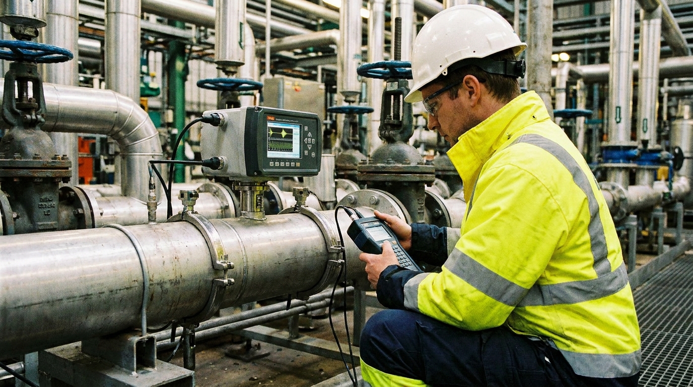
I. Scientific Site Selection and Standardized Installation Procedures
Measurement accuracy of radar Doppler flowmeters is highly sensitive to local flow hydraulics. Optimal installation requires selecting a straight, uniform reach where upstream flow is fully developed and downstream flow remains undisturbed. Ideally, the upstream straight section should extend 10–20 channel widths, while the downstream section should be at least 5–10 channel widths. Avoid locations near confluences, turbulent eddies, hydraulic jumps, or abrupt changes in cross-section geometry.
Step-by-Step Installation Protocol
Step 1: Mounting Structure Installation
Securely anchor the mounting bracket to stable infrastructure—such as bridge abutments, channel sidewalls, or cantilever arms—accounting for local wind loads and precipitation intensity. Structural rigidity is essential: any vibration or sway during extreme weather may introduce spurious Doppler signals and compromise velocity estimation.
Step 2: Probe Angle Adjustment
The radar velocity sensor must be oriented at the manufacturer-specified pitch angle (typically 30°–45°) relative to horizontal, ensuring optimal microwave incidence on the water surface and efficient backscatter capture from capillary and short gravity waves. For integrated radar water-level sensors, vertical alignment—perpendicular to the instantaneous water surface—is mandatory to ensure geometrically accurate distance measurements.
Step 3: Integrated Module Deployment
For multi-sensor stations equipped with onboard imaging capability, camera alignment must be coordinated precisely with the radar footprint. The field of view should fully encompass the radar-illuminated water surface area while simultaneously capturing reference features—such as staff gauges, fixed benchmarks, or calibrated scale markings—to enable video-assisted validation, remote recalibration, and AI-powered anomaly detection in centralized monitoring platforms.
II. System Commissioning and Parameter Calibration
Following physical installation, software-based commissioning ensures robust coupling between velocity and water-level measurements—critical for reliable discharge computation.
- Velocity Parameter Calibration: Input the actual mounting angle into the configuration software to enable automatic compensation for Doppler frequency shift errors induced by probe inclination. Additionally, apply an appropriate hydraulic coefficient (e.g., surface-to-mean velocity ratio), selected according to channel morphology, bed roughness, and flow regime—typically ranging from 0.75 to 0.95 for well-developed open-channel flows.
- Water-Level Reference Calibration: Use a certified portable ultrasonic level meter or manual staff gauge reading to obtain the true absolute elevation or depth datum. Enter this value as the zero-reference point in the system to align radar-derived distance measurements with surveyed vertical datums—ensuring traceable, metrologically sound water-level reporting.
- Cross-Sectional Geometry Input: Accurate discharge calculation relies on the product of measured mean velocity and real-time wetted area. Survey and input precise geometric parameters of the measurement section—including shape (trapezoidal, rectangular, U-shaped), bottom width, side slopes, and bankfull elevation. The system then dynamically computes wetted area from live water-level readings, enabling continuous output of instantaneous and cumulative flow volumes.
III. Routine Inspection and Preventive Maintenance
While non-contact radar technology eliminates risks associated with biofouling, sediment accumulation, and electrochemical corrosion, regular external maintenance remains indispensable for sustained performance. Ecolor Technology recommends monthly field inspections.
Sensor Surface Cleaning
Gently wipe radar antenna panels and camera lenses with a soft, damp cloth to remove dust, rain residue, or spider webs. Never use abrasive materials or corrosive solvents.
Power & Comm Check
Verify solar panel cleanliness; confirm battery voltage remains within nominal range (12–14 V DC); inspect all aviation connectors and IP68-rated waterproof junctions for looseness or moisture ingress.
Measurement Zone Clearance
Remove floating debris, vegetation, or woody obstructions directly beneath the sensor. Such objects cause diffuse radar scattering, degrading signal-to-noise ratio.
IV. Common Fault Diagnosis and Troubleshooting Methodology
Field-proven diagnostic logic enables rapid restoration of operational continuity:
1 Zero or Erratic Velocity Readings
Causes: Excessively quiescent water surfaces (insufficient wave energy) or wind-driven counter-current ripples masking true flow direction.
Action: Use the integrated camera feed to assess surface conditions. If flow is visible but no data appears, verify probe alignment; inadvertent angular displacement may deflect the radar beam away from the water surface.
2 Stagnant or Inaccurate Water-Level Data
Causes: Persistent fixed reflectors below the sensor (e.g., ice formation, exposed bedrock, accumulated debris).
Action: Clear obstructions or adjust the instrument’s “blanking zone” and effective measurement range via software configuration.
3 Data Transmission Failure or Video Loss
Causes: Power issues (shading, soiling, battery aging) or network registration failure.
Action: Measure mainboard supply voltage. If nominal, verify IoT SIM card balance and network status. Check antenna connections and LTE/4G module LEDs. Perform a controlled power cycle if necessary.
Conclusion
Reliable, high-fidelity operation of radar Doppler flowmeters hinges not only on superior hardware engineering—but equally on disciplined installation protocols, rigorous calibration discipline, and proactive maintenance practices. By adhering to standardized workflows—and leveraging the synergistic advantages of non-contact sensing and visual verification—water utilities, hydrological agencies, and environmental monitoring programs can achieve unprecedented levels of data continuity, precision, and decision-support reliability.