In-Depth Comparison of Four Technical Routes for Electromagnetic Flowmeters
Technical Analysis | Industrial Instrumentation
In process industries such as municipal water management, chemical, power, metallurgy, food and beverage, and new energy materials, electromagnetic flowmeters have long been used for the measurement and control of conductive liquids. Their enduring popularity stems from features like no moving parts, no flow obstruction, low pressure loss, and a wide turndown ratio.
With increasing demands for small bore sizes, corrosion resistance, lightweight design, and intelligence, the technological trajectory of electromagnetic flowmeters is shifting from a single "sensor + converter" model to segmented competition emphasizing materials, structures, excitation algorithms, and digital diagnostics.
This article compares the advantages, disadvantages, applicable scenarios, and selection recommendations of different technological routes, providing engineering references incorporating keywords such as LGF-PA66, injection-molded integrated design, corrosion resistance, and DN50.
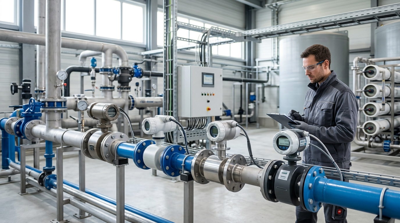
I. Divergence of Technological Routes: From General-Purpose Instruments to Scenario-Specific Components
Electromagnetic flowmeters operate based on Faraday's law of electromagnetic induction: when a conductive liquid flows through a magnetic field, it generates an induced electromotive force proportional to the average flow velocity. The electrodes collect the signal, which is then converted into volumetric flow rate by the converter. Although the principle is mature, engineering implementation requires the inner wall of the measuring tube to be insulated, the electrodes to maintain stable contact with the medium, the magnetic field to be uniform and controllable, and the housing to withstand pipeline stress.
Therefore, the differences among various technological routes are mainly reflected in medium adaptability, temperature and pressure boundaries, maintenance costs, and long-term stability.
Traditional vs. Modern Approaches
Traditional electromagnetic flowmeters mostly adopt a metal measuring tube with a lining structure, covering sizes from DN10 to over DN3000. The accuracy is typically Class 0.5, with some products reaching Class 0.2, and the flow velocity range is usually between 0.1 m/s and 10 m/s. Such solutions benefit from extensive engineering experience and are suitable for large-bore and complex industrial pipeline networks.
However, in scenarios involving small bores, strong corrosion, frequent disassembly, or lightweight requirements, lining flanging, electrode sealing, flange coaxiality, and assembly consistency introduce additional variables that affect long-term stability.
In recent years, routes such as ceramic measuring tubes, monolithic injection-molded engineering plastics, and capacitive electrodes have gradually matured. Taking DN50 as an example, this bore size is commonly found in dosing systems, circulating water branch pipes, small chemical units, and pilot lines. Users pay more attention to corrosion resistance reliability, small-flow stability, installation space, and maintenance convenience.
The LGF-PA66 monolithic injection-molded structure has gained more attention under such demands; it does not replace all solutions but provides an integrated option for specific operating conditions.
II. Mainstream Technological Routes
1. Lined Metal Tubes
Structure: Carbon steel/stainless steel housing with rubber or fluoroplastic lining. Covers a wide range of bore sizes (PN10-PN40). Suitable for wastewater, slurries, and acid-alkali solutions. Drawback: Assembly interfaces can lead to instability under negative pressure or thermal shock.
2. Ceramic Measuring Tubes
Material: Alumina ceramic. Features excellent insulation, wear resistance, and chemical corrosion resistance. Ideal for slurries and high-solid-content fluids. Limitation: Brittle and sensitive to mechanical impact and thermal shock; higher cost.
3. Monolithic Engineering Plastics
Material: Long glass fiber-reinforced polyamide 66 (LGF-PA66). Integrates tube, flanges, and seats via injection molding. Reduces part count and improves corrosion resistance. Best for DN15-DN100, ambient temperature, and medium-to-low pressure corrosive aqueous solutions.
4. Capacitive Non-Contact
Mechanism: Electrodes couple signals through the tube wall without direct liquid contact. Advantage: Reduces signal drift from electrode corrosion/fouling. Drawback: Weak signal sensitivity to material dielectric constants and temperature.
III. Comparison of Lining and Measuring Tube Materials
- Rubber Lining: Good elasticity, adapts to particle impact. Typical temp: 0°C–60°C (up to 80°C). Not suitable for high-temp steam or organic solvents. Cost-effective for DN50 municipal wastewater.
- Fluoroplastics (PTFE/PFA): Excellent chemical corrosion resistance. Temp range: 120°C–180°C. PTFE has cold flow tendencies; PFA offers better density but higher cost. Requires careful evaluation of negative pressure conditions.
- Ceramic Tubes: Outstanding wear and corrosion resistance. Smooth inner walls reduce adhesion. Limited by brittleness. Reliable for highly abrasive media if mechanical collision risk is managed.
- LGF-PA66 (Modified Plastic): Reinforced PA66 offers superior tensile strength (hundreds of MPa) and flexural modulus. Provides stable inner diameter dimensions and reliable electrode seat sealing. Suitable for anti-corrosion scenarios at ambient temperatures.
IV. Engineering Value of LGF-PA66 Monolithic Injection-Molded Structure
The primary value of the monolithic injection-molded structure lies in the reduction of assembly interfaces. In traditional designs, separate manufacturing of tubes, linings, and flanges creates potential leakage points. The LGF-PA66 structure uniformly controls the inner wall, electrode positions, and connections through molds, significantly improving batch consistency.
Lower density than metals reduces weight for dosing skids and elevated racks.
Continuous encapsulation reduces exposed metal areas and crevice corrosion risks.
Injection molding suits scaled production, reducing secondary assembly processes.
Note: The LGF-PA66 route is not omnipotent. Avoid use in steam purging, high-temperature CIP/SIP, or frequent negative pressure conditions.
V. Flow Range & Application Cases for DN50 Bore Size
DN50 is a typical small-bore specification. Based on an inner diameter of ~50 mm:
- Flow Velocity 1 m/s: ~7.07 m³/h
- Flow Velocity 0.5 m/s: ~3.53 m³/h
- Flow Velocity 3 m/s: ~21.2 m³/h
Industry Case Study: PAC Dosing System
A municipal water plant originally experienced housing rust and signal fluctuations in their Polyaluminum Chloride (PAC) dosing system due to salt spray and chemical accumulation. They switched to a DN50 corrosion-resistant electromagnetic flowmeter featuring:
- Measuring part: LGF-PA66 monolithic injection-molded structure
- Electrodes: 316L Stainless Steel
- Seals: FKM (Viton)
- Operating Conditions: 0.4–0.6 MPa, 5°C–35°C, Flow 2–8 m³/h
After 12 months of continuous operation, maintenance was limited to regular electrode cleaning and grounding checks.
Installation Criticalities
For DN50 applications, ensure sufficient straight pipe sections (Upstream ≥ 5D, Downstream ≥ 3D). Install in full-pipe position (vertical flow bottom-to-top recommended). Proper shielding and grounding are essential to avoid interference from frequency converters and metering pumps.
VI. Selection Recommendations
- Medium Conductivity: Ensure conductivity ≥ 5 µS/cm. For pure water/oil/gas, consider capacitive solutions or other technologies.
- Temperature & Pressure: Ambient/Medium pressure → Rubber or Engineering Plastic. High Temp (>100°C) or High Pressure → Metal Lining, PFA/PTFE, or Ceramic.
- Electrode Matching:
- 316L: Clean water, weakly corrosive.
- Hastelloy C: Oxidizing acids, chlorine environments.
- Titanium: Chlorides.
- Tantalum: Strong acids (avoid strong alkalis).
- Wear & Hygiene: Slurries → Ceramic/Wear-resistant rubber (2–4 m/s). Food/Pharma → Smooth, dead-corner-free structures compatible with CIP/SIP.
VII. Concluding Outlook
From an industry trend perspective, competition for electromagnetic flowmeters is shifting from single measurement accuracy to systems engineering capabilities. On the materials front, long glass fiber-reinforced plastics and modified fluoromaterials are pushing boundaries. Digitization adds value through empty pipe alarms, conductivity monitoring, and remote O&M.
For small-bore anti-corrosion applications like DN50, combining the LGF-PA66 monolithic injection-molded structure with intelligent converters is expected to form more mature solutions in dosing, circulating water, and fine chemicals.
Ultimately, regardless of technological evolution, selection must return to operating conditions: conductivity, temperature/pressure matching, corrosion control, and maintenance convenience remain the definitive criteria for judgment.

