Electromagnetic Flowmeters in Water Distribution Networks: Engineering Practices for Accuracy and Long-Term Stability
Technical Guide | Industrial Instrumentation
Introduction: Why Electromagnetic Flowmeters Dominate Water Network Metering
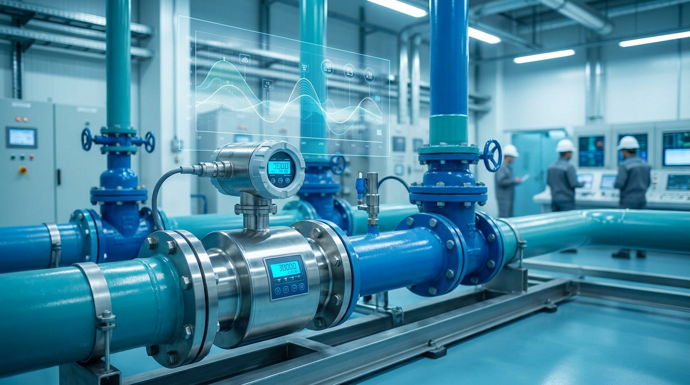
In urban water distribution networks and DMA (District Metered Area) implementations, the accuracy of flow data directly governs leakage assessment accuracy and network scheduling decisions. Electromagnetic flowmeters, operating on Faraday's law of electromagnetic induction, offer measurement principles inherently independent of fluid density, viscosity, or temperature variations. Under full-pipe conditions, achievable accuracies reach ±0.5% or even ±0.2% of reading, making them one of the most widely adopted metering technologies in municipal water systems.
However, field installations frequently report zero drift, signal fluctuation, and measurement deviation issues. These are rarely inherent instrument defects — more often, they trace back to engineering errors in selection or installation practices. This article addresses four critical engineering dimensions for electromagnetic flowmeter deployment in water supply networks.
I. Sensor Sizing: The Decision Logic Beyond Nominal Pipe Diameter
Flowmeter sizing cannot simply mirror the pipe's nominal diameter. Two common scenarios in water networks demand careful analysis:
- Low-flow conditions: When nighttime minimum flow drops to 10%–20% of design capacity, a same-diameter meter may operate below its 0.3 m/s measurement threshold. In such cases, reduced-bore installation — fitting a DN150 sensor in a DN200 pipeline via reducer fittings — elevates velocity into the optimal measurement range.
- Lining material selection: Raw water transmission lines typically warrant rubber lining (superior abrasion resistance), treated water lines may use PTFE lining (chemical resistance), while high-sand-content sources demand polyurethane lining. Incorrect lining selection can cause lining degradation or delamination within 3–5 years, rendering the meter inoperative.
II. Installation: Straight-Run Requirements and Full-Pipe Assurance
While electromagnetic flowmeters tolerate shorter straight-run lengths compared to ultrasonic or vortex meters, minimum requirements of 5D upstream and 3D downstream (where D is sensor diameter) must still be observed. Near pump discharge points, extending the upstream straight run to 10D or more is recommended to mitigate pump-induced flow profile disturbances.
Critically, full-pipe conditions are non-negotiable. Electrodes must remain submerged at all times.
The following installation locations must be avoided:
Preferred installation positions are vertical pipes (upward flow) or the lower-mid section of horizontal pipes. In retrofit projects where ideal positioning is constrained by site conditions, models equipped with empty-pipe detection capability should be specified to promptly identify non-full-pipe states.
III. Grounding and EMI Immunity: Signal Stability in Pump Station Environments
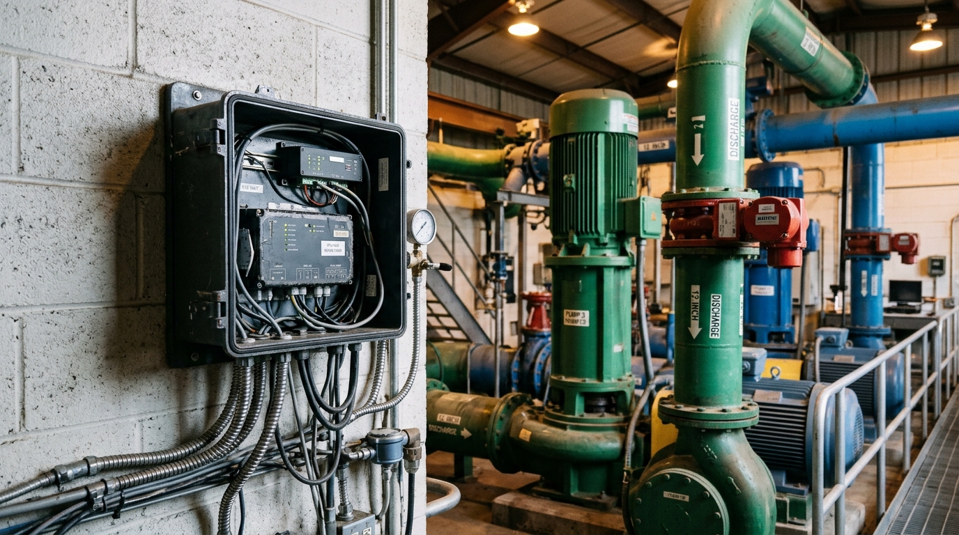
The induced electromotive force in electromagnetic flowmeters typically measures in the millivolt range, making it highly susceptible to external electromagnetic interference. In pump rooms with substantial electrical equipment, grounding design directly determines measurement stability.
Proper grounding methodology encompasses:
- Independent grounding: The flowmeter ground must be isolated from power equipment grounding, with ground resistance ≤4Ω.
- Grounding rings/electrodes: When pipelines are constructed from non-conductive materials (PE, PPR), grounding rings are mandatory to close the signal circuit loop.
- Shielded cabling: Signal cables must employ braided-shield twisted pairs, with the shield grounded at a single point (typically at the converter end).
Field Insight: Approximately 60% of signal fluctuation issues originate from inadequate grounding or improper cable selection. We recommend verifying signal-to-noise ratio at the electrode output using an oscilloscope during commissioning.
IV. Long-Term Maintenance and Accuracy Verification
While electromagnetic flowmeters are classified as maintenance-free instruments, this does not equate to "install and forget." Recommended maintenance intervals include:
Every 6 Months: Zero-point Drift Check
With the downstream valve closed under static full-pipe conditions, record the zero reading. Recalibrate if offset exceeds 0.5% of full scale.
Annually: Inspect Electrode Surface
In waters with elevated iron and manganese content, electrode oxidation layers can attenuate the signal. Portable calibrators enable in-situ verification.
Comprehensive Lining Inspection
Particularly on pipelines experiencing significant temperature fluctuations, where thermal cycling accelerates lining aging.
Conclusion
Deploying electromagnetic flowmeters in water distribution networks appears straightforward, but sustaining high accuracy from commissioning through years of operation requires correct execution at every stage — selection, installation, grounding, and maintenance. For DMA metering programs and smart water initiatives, flow data reliability underpins all downstream analytics and decision-making. We recommend establishing detailed instrument technical specifications at project inception, incorporating the engineering practices outlined above into acceptance criteria to prevent costly rework.