Why Non-Contact Radar Dominates Reservoir Monitoring
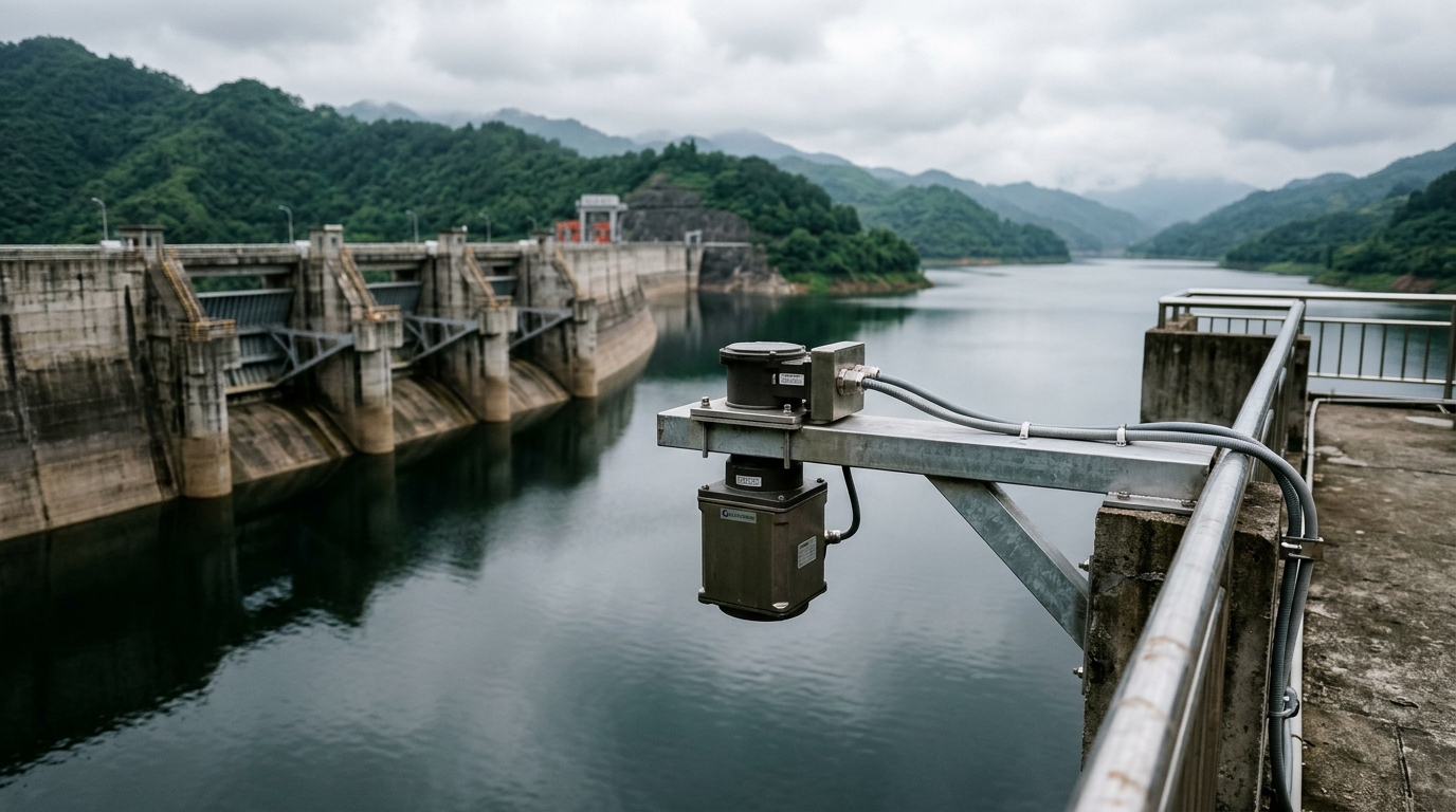
Reservoirs are the backbone of flood control, dam safety and raw water supply telemetry. Compared with submersible pressure transducers or float-driven shaft encoders, 26 GHz and 80 GHz FMCW radar level meters measure without contact — immune to water quality, sediment, floating debris and velocity. Mounting on a dam crest bracket turns weeks of civil works into a one-day retrofit. However, reservoir sites introduce specific challenges: long ranges (30–70 m), wind-driven waves over open water, and strong multipath reflections from spillway gates, steel hoists and railings. Selection and commissioning must address these conditions explicitly.
Three Selection Criteria That Matter
- Beam angle and footprint: An 80 GHz planar microstrip antenna achieves a beam angle of 8° or less. At a 30 m mounting height this yields a footprint of roughly 4.2 m on the water surface, keeping shoreline vegetation and debris outside the main lobe. A 26 GHz horn antenna (12°–15° beam) expands the footprint beyond 8 m, where wave reflections and flotsam are more likely to corrupt the echo.
- Dead zone at high water: Flood season operation near spillway crest requires a near-field blind zone below 0.3 m; otherwise the highest water stage falls inside the dead zone exactly when data matters most. Verify the specified minimum measuring distance and add margin in bracket height design.
- Multipath rejection: Concrete dam faces and steel gate structures are powerful reflectors. Prefer instruments with echo-curve diagnostics and configurable tracking/suppression windows, so the measurement window locks onto the true water-surface echo.
Field Installation and Commissioning
Mounting: Use a cantilever stainless-steel bracket projecting at least 0.5 m beyond the dam crest barrier, with the beam axis clear of gate hoist ropes and handrails. Check the bracket's natural frequency against wind excitation and add diagonal bracing where needed.
Commissioning: Capture the echo curve during a calm-water period; confirm the surface peak SNR ≥ 20 dB, then set the tracking window to ±1 m around the still water level. Enable median filtering and rate-of-change limiting (reject single samples jumping >5 cm as wave noise). Before the flood season, cross-check at least three stages against a manual staff gauge — agreement within ±1 cm is the acceptance criterion under IEC-referenced hydrological practice.
Power and telemetry: For unattended sites, solar-plus-LiFePO4 packs sized for five consecutive overcast days are standard, feeding a 4G/NB-IoT IoT RTU. In lightning-prone basins, install surge protection on feeder lines and maintain equipotential grounding with resistance ≤4 Ω.
Summary
A successful reservoir radar deployment comes down to engineering discipline: a narrow-beam 80 GHz instrument, a compliant bracket, echo-window tuning and pre-flood-season gauge validation deliver data availability above 99%. As low-cost radar modules scale up, dense coverage of county-level reservoir clusters is becoming economically realistic for smart water utilities.