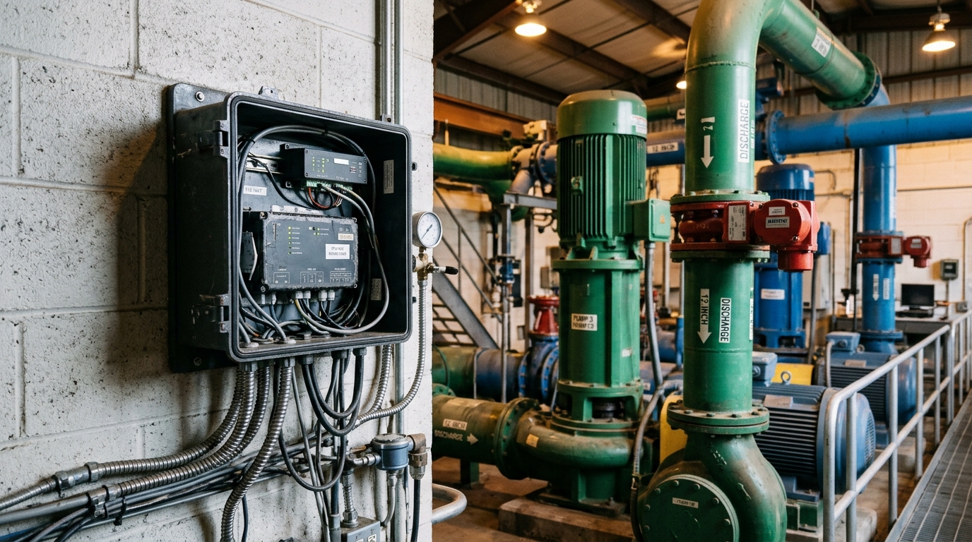
Pump stations are the heart of urban water supply and drainage systems, and among the most common targets for unmanned-operation retrofits. Compared with hydrological gauging stations or manhole monitoring points, the pump station environment has three defining characteristics: a harsh electromagnetic environment (VFDs and soft starters generate severe conducted and radiated interference), reliable mains power (no solar budgeting needed, but outage handling is), and tightly coupled monitoring and control duties. This article distils the key engineering points for deploying IoT RTUs in pump stations, based on a county-level drainage pump station retrofit.
1. Electrical environment assessment and interference mitigation
Starting 30–160 kW pump sets produces contactor arcing and VFD PWM transients; measured bus voltage distortion can exceed 8%. Three practices are essential:
- Power isolation: feed the RTU from a UPS or a dedicated control circuit with an upstream surge protective device (SPD, In ≥ 20 kA, 8/20 µs waveform); use a wide-range DC input (9–36 V) or an isolating transformer.
- Signal isolation: route analogue inputs (4–20 mA level and pressure transmitters) and digital inputs (run/fault status, gate limit switches) through opto-isolated I/O; segregate I/O and power terminals by at least 100 mm inside the cabinet.
- Grounding and shielding: bond the RTU enclosure to the station ground grid with a dedicated 4 mm² conductor; use twisted-pair shielded cables with single-point shield grounding, routed in separate trays from power cables (≥300 mm parallel separation, 90° crossings).
Select equipment tested to the IEC 61000-4 immunity series (ESD ±8 kV contact, EFT/burst ±2 kV, surge ±2 kV) and IEC 60068-2 environmental tests, with IP65 as the minimum enclosure rating.
2. Communications: dual primary/backup links are the baseline
Pump stations often sit in peri-urban areas or underground chambers where 4G coverage is uneven. The robust pattern is a primary 4G Cat.1 link plus an NB-IoT (or fibre/Ethernet) backup: the primary carries second-level telemetry and control commands, while the backup maintains heartbeats and critical alarms for a few dollars of monthly data cost. Measure RSRP on site before fixing the antenna design — an external magnetic-mount antenna typically gains 8–12 dB over an in-cabinet antenna. Prefer MQTT over TLS; use change-of-value reporting with timestamps plus a periodic full scan (e.g. every 15 min), and ensure the RTU buffers at least 30 days of data for store-and-forward during outages.
3. Pump set status acquisition and energy metering
The core of pump station telemetry is asset health, not just level. A minimum point list includes: inlet/outlet levels (radar or hydrostatic), per-pump run status and accumulated run hours, current/voltage/active power via a three-phase revenue-grade meter on RS-485 Modbus-RTU, winding temperature and vibration (optional wireless sensors), and suction/discharge pressure. When CT secondaries feed RTU analogue inputs, verify ratio and range matching (200/5 A is common, mapping to a 0–5 A input) to avoid saturation and metering error.
4. Retrofit case and field lessons
A county-level drainage station with three 75 kW submersible axial-flow pumps was previously manually attended. The 2025 retrofit used one IoT RTU (16 DI / 8 AI / 8 DO) plus smart meters to implement level-based automatic pump staging, SMS fault alarms and remote/local mode switching. Manning dropped from two shifts of four operators to periodic inspection, and specific energy consumption fell about 11% through time-of-use pump scheduling. Three lessons: (1) digital outputs controlling pump sets must pass through interposing relays, with a hardwired remote/local selector giving local priority — this is a non-negotiable safety baseline; (2) use dual-redundant level measurement (radar + hydrostatic) with cross-checking to prevent false starts/stops from single-sensor drift; (3) fully document the legacy PLC or relay logic before cutover, and where RTU strategies conflict with existing safety interlocks, safety logic wins.
Conclusion
Deploying RTUs in pump stations is fundamentally about building reliable data and control channels under strong electromagnetic and safety constraints. Hold to four keywords — isolation, dual links, local priority, redundancy — and a standardised point list, and unmanned operation with fine-grained energy management becomes a low-cost reality.