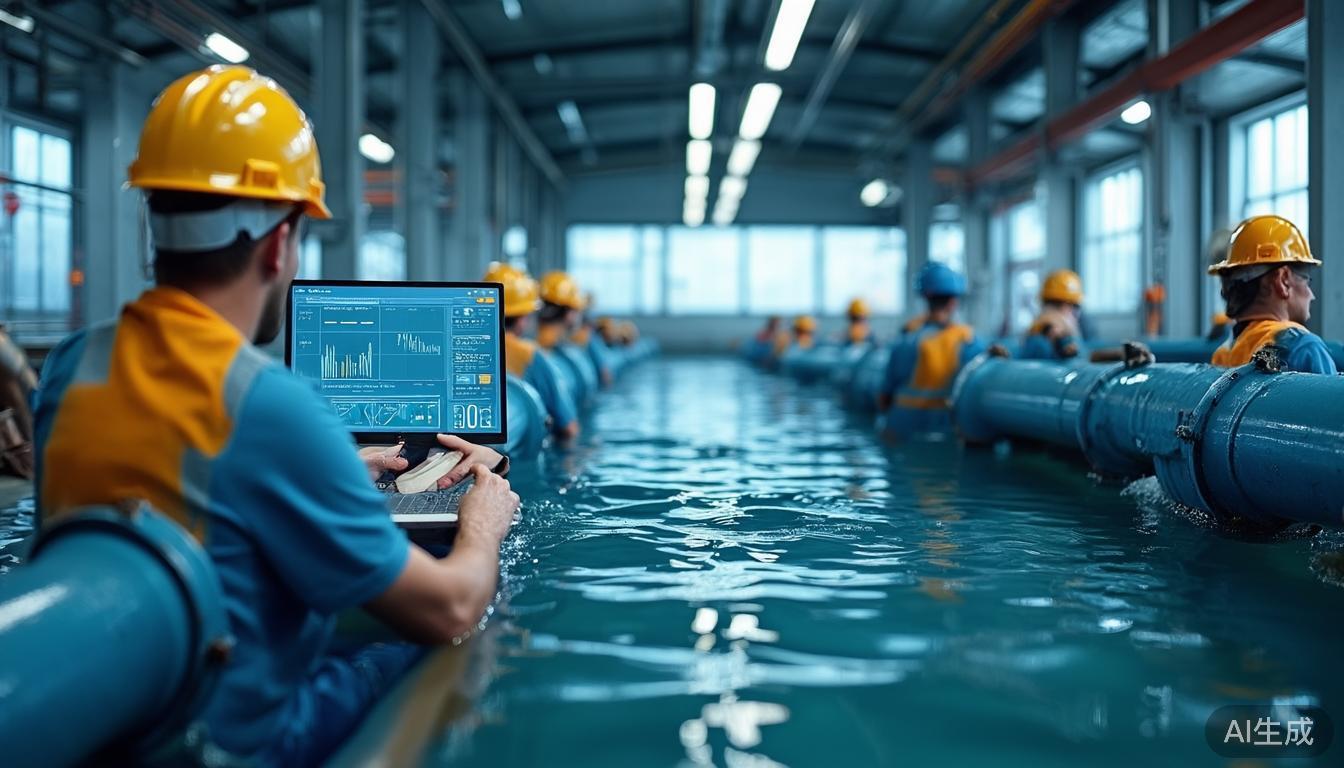
End-to-End Guide for Installation and Commissioning of Urban Waterlogging Early Warning Systems
In recent years, short-duration heavy rainfall has become increasingly common, causing rapid water accumulation in urban spaces. Once waterlogging exceeds safety thresholds at locations such as underpasses, tunnels, low-lying intersections, and underground garage entrances, it disrupts traffic, power supply, communications, and residents' daily lives.
Urban waterlogging warning has evolved from simple meteorological forecasting into a closed-loop engineering process encompassing "on-site sensing—threshold judgment—rapid dissemination—flood control response."
This guide focuses on water accumulation monitoring, warning dissemination, radar water level sensing, and flood control linkage. It specifically addresses where to install equipment, how to install and commission it, and how to maintain and troubleshoot it in the later stages. The parameters cited are derived from typical urban flood control projects and serve as a practical reference for sub-district offices, industrial parks, municipal O&M units, and emergency management teams.
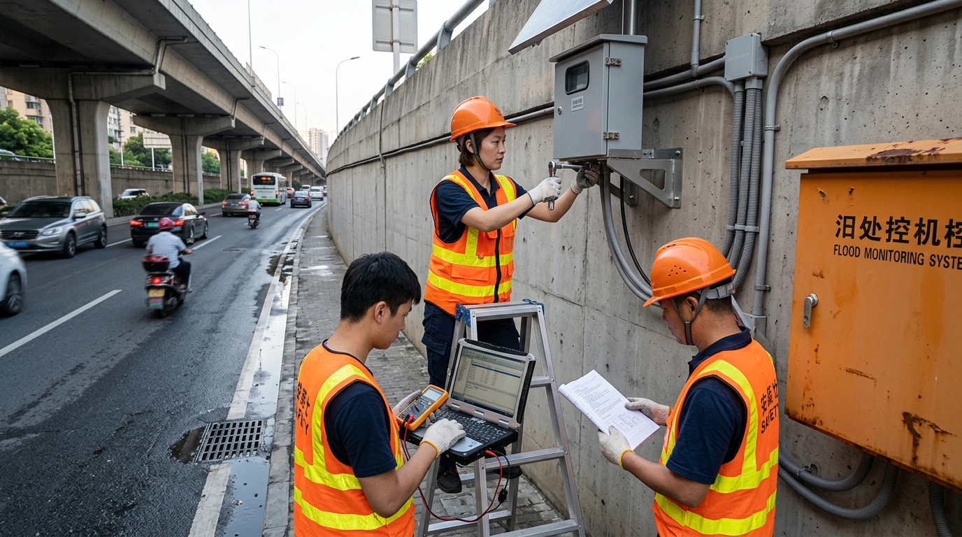
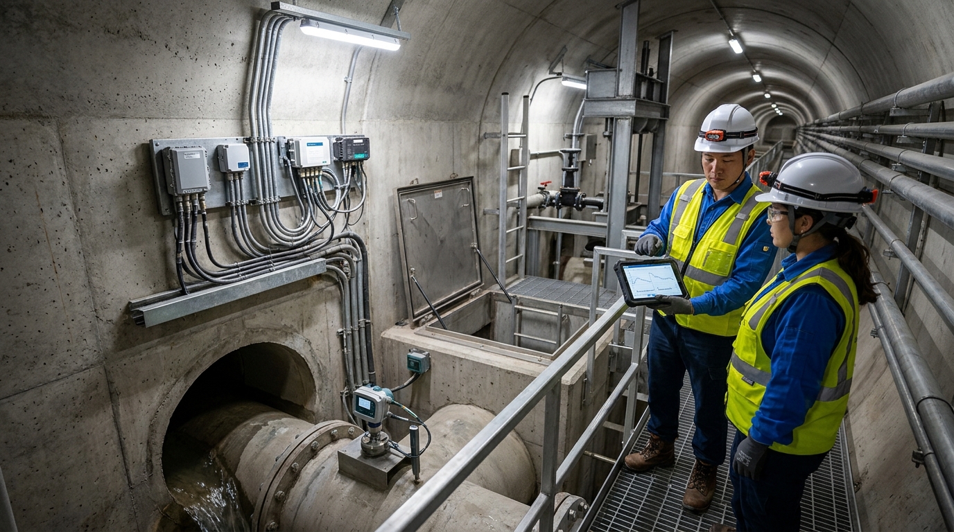
It should be noted that waterlogging warning is not a single device, but a system comprising radar water level gauges, water accumulation sensors, rain gauges, video verification, power and communication modules, warning platforms, and on-site response mechanisms. Only by standardizing installation, commissioning, maintenance, and fault handling can warning information be made timely, accurate, and accountable.
1. System Composition: Sensing, Monitoring, and Linkage
The urban waterlogging warning system is typically divided into four layers:
- Perception Layer: Collects data on water accumulation depth, water level, rainfall, and on-site images.
- Transmission Layer: Transmits data back via 4G, 5G, NB-IoT, wired fiber optics, or BeiDou short messages.
- Platform Layer: Handles data cleaning, threshold judgment, map display, and warning push notifications.
- Execution Layer: Links with audible and visual alarms, LED warning screens, broadcasting systems, barrier gates, pump stations, and traffic control devices.
Radar Water Level Gauges
Among water accumulation monitoring devices, radar water level gauges are being increasingly widely used. Common 80GHz radar water level gauges have a measurement range of 0 to 15 meters or 0 to 20 meters, with an accuracy of ±3 mm to ±5 mm and a blind zone typically less than 0.3 meters. They are suitable for underpasses, bridges and culverts, riverbanks, and low-lying roads.
The advantage of non-contact radar measurement lies in its resistance to interference from floating objects, sewage, and short-term submersion; however, the installation angle and clearance conditions directly affect data quality.
Dual-Sensor Configuration
Projects typically adopt "radar + electronic water ruler" or "radar + hydrostatic water level gauge" to improve reliability.
Four-Level Thresholds
- Attention: 15 cm
- Warning: 25 cm
- Traffic Control: 35 cm
- Road Closure: 50 cm
Key indicators for warning dissemination include reporting interval, alarm delay, and delivery rate. During the non-flood season, the reporting interval can be set to 10 to 30 minutes; during the flood season, it is shortened to 1 minute, and further reduced to 30 seconds during heavy rainfall. The time from the platform receiving data to disseminating SMS, APP push notifications, or on-site broadcasts should be controlled within 60 seconds.
2. Pre-Installation Survey: Site Selection and Infrastructure
A risk point survey must be conducted prior to installation. Priority should be given to locations with obvious historical water accumulation, complex drainage paths, and significant traffic impact, such as the lowest points of overpasses, tunnel entrances, culverts, riverside roads, underground garage ramps, areas around subway entrances, and exits of large parking lots.
Radar Clearance and Installation Height
The installation clearance of the radar water level gauge determines measurement stability. The sensor should be aimed vertically at the water surface or the expected water accumulation surface, avoiding trees, billboards, guardrails, bridge crossbeams, cables, and large metal structures.
Rule of Thumb: Installation height is typically more than 0.5 meters above the historical maximum water accumulation depth. If the maximum possible water accumulation is 1.2 meters, the radar installation height can be set to 1.8 to 2.5 meters.
Power and Communication
Power supply and communication are the two major challenges in on-site deployment.
- Mains Power: Use 220V AC converted to 12V or 24V DC via a switching power supply, equipped with a surge protector.
- Solar Power: Typical configuration includes a 30W to 50W solar panel, a 20Ah to 40Ah battery, and a 10A to 20A charge/discharge controller. For 7 days of overcast weather, increase battery capacity and enable low-power mode.
- Communication: 4G/5G signal strength should be no lower than -95dBm. Below -105dBm, consider external antennas, NB-IoT, or BeiDou short messages.
3. Installation Steps: Standardized Process
Construction Preparation
Set up barriers and warning signs. Check equipment lists including radar gauges, RTU terminals, batteries, solar panels, antennas, and waterproof connectors. Inspect appearance and waterproof seals before power-on.
Foundation and Pole Construction
Determine foundation pit dimensions based on pole height and geology. Control verticality deviation within 3‰. Ensure cable routing holes are reserved and conduits are protected from wear.
Installing the Radar Water Level Gauge
Install pointing vertically downward. Keep antenna surface clean and maintain a distance of no less than 0.5 meters from side walls or reflective surfaces. Avoid oblique installation if possible; if necessary, set slant distance compensation according to the manual.
Verification Sensors and Terminals
Fix electronic water rulers along poles/walls with clear scale correspondence. Arrange strong current, weak current, lightning protection, and terminal blocks in separate zones inside the control box. Install LED screens and alarms in visible positions for approaching traffic.
4. Commissioning Methods: Calibration and Testing
The first step of commissioning is device parameter configuration. Configure station ID, latitude/longitude, device type, SIM card number, platform address, and reporting protocol (MQTT, HTTP, Modbus RTU to TCP, etc.).
Radar Calibration
Use a temporary water ruler or known elevation point for on-site verification. Measure the empty height from the radar installation height to the ground, then compare with the value displayed on the platform after water accumulation.
Three-Point Calibration Method
- Dry state
- 10 cm water depth
- 30 cm water depth
If the error exceeds ±2 cm, check installation angle, reflective surface interference, and filtering parameters.
Filtering and Debouncing
Vehicle splashing, pedestrian passage, and floating debris can cause instantaneous jumps. It is recommended to use 8 to 16 times averaging and set a continuous confirmation time of 10 to 30 seconds. Alarm triggering should not be "instantaneous upon a single spike" to avoid false alarms and public alert fatigue.
5. Routine Maintenance: Inspection and Care
"Construction accounts for 30%, while O&M accounts for 70%."
During the non-flood season, monthly inspections are recommended; during the flood season, weekly inspections are advised. Inspection items include checking if the radar radome is dirty, if solar panels are covered with dust, if cameras are misaligned, if poles are loose, and if equipment boxes have water ingress.
Cleaning Frequency
Dust, oil stains, and bird droppings degrade radar echo quality or charging efficiency. Use a soft cloth and neutral detergent. Avoid hard objects to prevent scratches.
Battery Management
Check voltage regularly. Lead-acid below 11.8V or lithium below set protection requires investigation. Batteries over 3 years old should undergo capacity testing; replace if below 70% nominal value.
Platform-side maintenance is equally important. Verify station online rate, data completeness rate, and alarm records monthly. Before the flood season each year, conduct drills for thresholds, contacts, SMS templates, and linked equipment to ensure warnings reach traffic police, sub-district offices, and rescue personnel.
6. Common Fault Troubleshooting
Data Loss / Station Offline
Troubleshooting Sequence: Power → Communication → Terminal → Platform. Check control box output voltage, RTU indicator lights, SIM status, APN, domain name, port, and firewall. If multiple stations go offline, check the platform or operator network.
Radar Data Jumping
Causes: Non-vertical installation, dripping water, nearby metal reflections, dirty radome, vehicle splash. Solution: Check raw echo strength, temperature compensation, recalibrate empty height, and increase alarm confirmation time to 20 seconds.
False Alarms
Causes: Leaves/debris covering water ruler, brief vehicle splash, residual water films, damp wiring, low thresholds. Solution: Add verification logic (radar vs. electronic ruler), require threshold exceeded for 30 continuous seconds, combine with rainfall trend judgment.
Missed Alarms / Delays
Causes: Silt blockage, large radar blind zones, communication dropouts without retransmission, low-power shutdown. Solution: Enable local storage and breakpoint resume transmission for critical locations.
Lightning and Water Ingress
Check power/signal lightning arresters, grounding resistance (<10Ω, <4Ω for critical sites), and box sealing. If water ingress occurs, cut power, dry, replace seals, and generate an O&M work order.
7. Cases and Outlook
Case Study: East China High-Tech Zone
Deployed radar water level gauges, electronic water rulers, rain gauges, and video surveillance at 38 low-lying intersections. Utilized 80GHz radar (0-10m range, ±5mm accuracy) with solar power (40W PV, 30Ah battery). Three-level thresholds set at 15cm, 25cm, and 40cm. During the 2024 flood season, 117 valid warnings were triggered with an average alarm delay of ~45 seconds.
Case Study: South China Underpass Remediation
Installed radar gauges and dual-channel communication at an underpass tunnel. Automatic pump start at 20cm; LED/barrier linkage at 35cm. After one flood season, traffic disruption duration decreased by ~40%, and O&M arrival time shortened from 35 to 18 minutes.
Future Outlook
Urban waterlogging warning will evolve from "post-accumulation alarming" to "pre-rainfall prediction, dynamic correction during rainfall, and post-accumulation review." Integration of site radar, video AI, pipe network liquid levels, river water levels, short-term meteorological forecasts, and urban drainage models will form the digital foundation for urban flood control.
There is no once-and-for-all solution for urban waterlogging governance, but every accurate warning, every timely road closure, and every rapid drainage operation can reduce risks and minimize losses.