Proper Usage of Urban Waterlogging Early Warning Under Complex Operating Conditions
A practical guide to sensor installation, debugging, and O&M for urban flood control.
01 Introduction: Refined Operation and Maintenance
In recent years, short-duration heavy rainfall, outer rainbands of typhoons, and localized severe convective weather have occurred frequently. Urban low-lying sections, underpass interchanges, tunnel entrances, and entrances/exits of underground spaces are more prone to sudden water accumulation. For urban flood control management, waterlogging risk depends not only on rainfall but is also closely related to drainage capacity, surface runoff, pipe network backwater, river water levels, and on-site traffic organization. Once water accumulation exceeds the safe boundary for road traffic, it can quickly escalate into public safety issues such as trapped vehicles, endangered personnel, and traffic disruptions. Therefore, urban waterlogging warning is shifting from "post-rain patrols" to "in-rain monitoring, early warning, and rapid response."
In actual construction, radar water level meters, radar ranging sensors, electronic staff gauges, video surveillance, and rain gauges are widely used in water accumulation monitoring scenarios. Among these, radar devices have become a crucial perception means for urban water accumulation warning systems due to their non-contact measurement, minimal impact from water quality, ability to operate at night, and suitability for long-term outdoor deployment. However, equipment selection, installation location, debugging parameters, power and communication supply, and subsequent maintenance directly affect warning quality. Improper installation may lead to data jumps; unreasonable threshold settings may cause missed or false alarms; and inadequate maintenance may render the warning system ineffective during critical rainfall events.
Based on common urban flood control scenarios, this article reviews the installation steps, debugging methods, routine maintenance, and common troubleshooting of water accumulation warning systems, forming an actionable practical guide. The parameters involved refer to common industry engineering configurations; specific projects should be based on design documents, equipment manuals, and local flood control plans.
02 System Composition and Selection Points
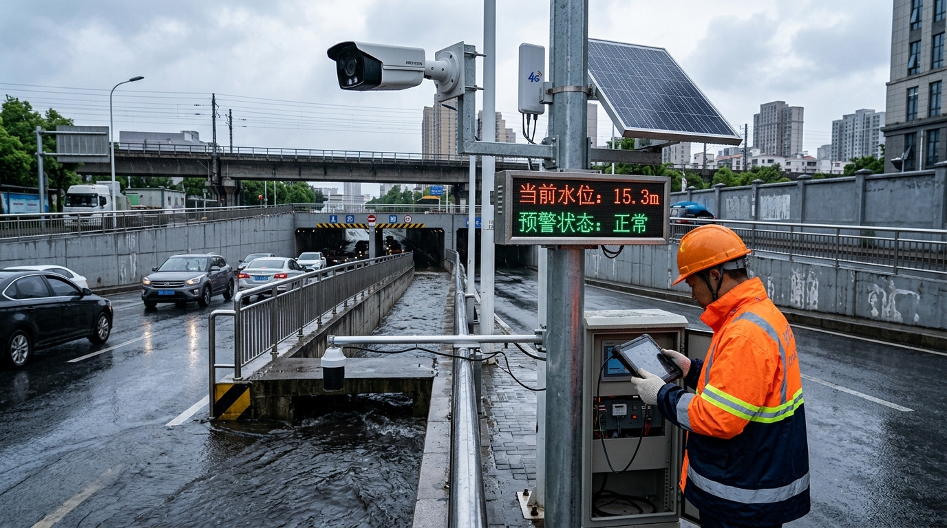
A complete urban water accumulation warning system typically includes the front-end perception layer, data transmission layer, platform application layer, and linkage disposal layer. The core of water accumulation warning is not merely "seeing the water," but translating water level changes into actionable warning responses.
Sensor Selection Strategy
- 80GHz FMCW Radar: Recommended for urban underpass interchanges, tunnel entrances, and low-lying intersections. Typical measuring range covers 0.3m to 15m with accuracy of ±3mm to ±10mm and a narrow beam angle (approx. 3 degrees), suitable for environments with numerous obstructions.
- 26GHz Radar: Suitable for more open areas but generally less effective than 80GHz in complex scenarios with bridges, culverts, railings, and green belts where anti-interference is key.
- Protection Rating: IP67 is standard; IP68 is advisable for long-term outdoor points. Operating temperature should cover -20°C to 70°C.
Power and Communication
Municipal power is stable for pump stations and existing pole resources. Solar panels (20W-60W) combined with lithium batteries (LiFePO4 or gel) are ideal for intersections without grid access, designed for 5-7 days of continuous rainy weather endurance. Communication methods include 4G, NB-IoT, LoRa, fiber optics, or wired Ethernet. For key points, local storage caching for over 7 days is recommended to handle communication interruptions.
Threshold Configuration
Thresholds are management parameters, not just equipment settings. Common four-level thresholds for ordinary roads are 50mm, 100mm, 200mm, and 300mm. For high-risk areas like underpasses, stricter grading (e.g., 150mm, 250mm, 350mm, 450mm) is adopted. It is critical to link these thresholds with traffic control, pump station operations, and emergency dispatch to form a closed loop.
03 Pre-installation Survey and Point Layout
The on-site survey determines the quality of monitoring points. Key considerations include historical water accumulation data, deepest water locations, drainage outlet positions, and traffic impact.
Underpass Interchanges
Focus on the lowest point, approach road low points, pump station sump forebay, and vehicle stagnation areas.
Underground Garage Entrances
Pay attention to ramp low points, water-retaining ridge locations, and rainwater backflow direction.
Point Layout Principles:
- Representativeness: Deploy sensors where water first reaches dangerous depths, avoiding high/edge locations chosen solely for convenience.
- Easy Maintenance: Ensure safe access for personnel, avoiding fast-traffic zones without safety islands.
- Convenient Linkage: Align points with on-site warning screens, traffic signals, and video surveillance for rapid response.
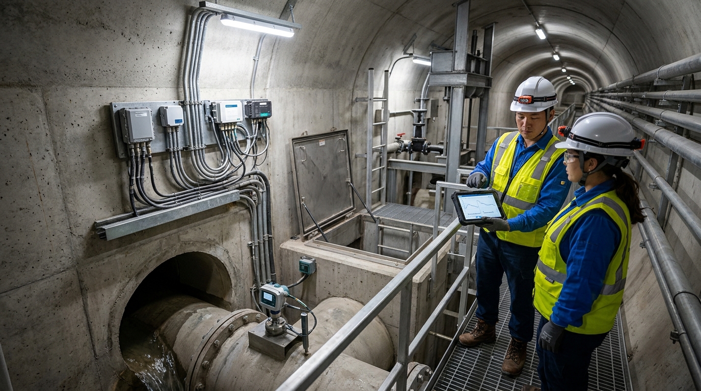
For typical underpasses, set up three types of points: bridge/culvert lowest point (radar sensor), entrance approach road (trend identification), and pump station forebay (linkage). If the length exceeds 80 meters, add points at both ends and the middle.
04 On-site Installation Steps
- Foundation and Pole Erection: Use C25 concrete foundations (400mm×400mm×600mm). Anchor bolts (M16/M20) calculated based on wind load. Verticality deviation < 3/1000. Check load-bearing capacity if mounting on existing structures.
- Radar Sensor Installation: Aim vertically/near-vertically. Bottom of antenna should be ≥0.5m from max water surface and 2.5m–4.0m from ground/deck. Avoid facing drainage outlets, vortex areas, or dense railings directly (offset ≥0.5m).
- Beam Path Inspection: Ensure no continuous obstruction. With a 4m height and 3-degree angle, beam radius is ~0.1m–0.2m. Keep ≥0.5m clearance around the beam center. Verify strongest echo comes from the water surface, not obstacles.
- Power and Cable Laying: Use galvanized/PVC/PE pipes. Outdoor joints must be IP67/IP68 waterproof. Label cables clearly. Solar panel tilt angle based on latitude; increase for self-cleaning in dusty areas.
- Lightning Protection and Grounding: Install surge protectors. Ground resistance ≤10 ohms (≤4 ohms for key points). Use hot-dip galvanized steel or copper-clad rods. Ensure equipotential bonding on metal bridge structures.
- Identification and Archiving: Attach nameplates with point name, number, contact, and date. Retain photos, coordinates, elevation, and wiring records for future troubleshooting.
05 Debugging and Acceptance Methods
Making water accumulation warning data trustworthy, usable, and linkable involves five critical steps:
- Parameter Configuration: Set reporting frequency (5-10 min normal, 1 min rain, 10-30 sec alarm). Input installation height and datum for accurate depth conversion.
- Static and Dynamic Calibration: Static: Collect 30+ sets of data on still water. Dynamic: Compare with staff gauge/video during controlled discharge. Target error: ±1cm to ±3cm.
- Threshold Setting: Define 4-level warnings (Prompt, Alert, Control, Emergency) based on road type and traffic. Add "duration" logic for underpasses (e.g., >250mm for 5 mins).
- Linkage Testing: Test full-link delay (sensor to action) within 30s–2 mins. Verify SMS/APP pushes, LED screens, traffic signals, and pump station starts.
- Acceptance: Conduct 72-hour trial operation. Metrics: Data integrity ≥99%, Alarm accuracy ≥95%, False alarm rate ≤5%.
06 Routine Maintenance and Pre-flood Inspection
Maintenance cycles must match the rainy season. Establish a mechanism of "monthly routine inspection, pre-flood special inspection, in-rain key patrol, and post-rain review."
Key Maintenance Focus Areas
- Radar Antenna: Clean dust/mud/bird droppings with soft cloth and neutral detergent. Check for cracks or condensation.
- Bracket & Pole: Check for loose bolts, rust, or tilt. Re-measure installation height quarterly to account for vegetation growth or construction changes.
- Power System: Clean solar panels monthly. Monitor battery voltage (12V system should stay >12.6V float charge). Check controllers for heating or oxidation.
- Communication: Daily check of platform heartbeats. Generate work orders if no data for 15 minutes. Backup platform configurations regularly.
Pre-flood inspections should use a checklist covering cleaning, tightening, voltage, signal, thresholds, and grounding. Rectify issues affecting data accuracy within 48 hours and flood-season alarm issues within 24 hours.
07 Common Troubleshooting and Handling
No Data / Offline
Sequence: Power → Communication → Equipment → Platform. Check indicator lights, SIM status, and antenna connections. If multiple points fail, check server/network first.
Data Jumping / Fluctuation
Causes: Vehicle splash, drainage flow, branch swaying, condensation. Solution: Check echo intensity curve. Increase filtering window or raise echo threshold. Adjust position if fixed obstacle reflection occurs.
Long-term High/Low Depth Error
Causes: Bracket settlement, pole tilt, datum change (road overlay). Solution: Measure actual distance with tape/staff gauge. Recalibrate if deviation exceeds allowable range.
False/Missed Alarms
False: Caused by mist, watering, wakes. Reduce via duration judgment and video verification. Missed: Caused by high thresholds or blocked sensors. Verify alarm push delivery and linkage modes before flood season.
08 Case Reference: Practical Effects
A southern city renovated a waterlogging-prone area with 3 underpasses, 2 riverside roads, and 5 garage entrances. The project deployed 48 radar units, 12 rain gauges, and 26 video channels linked to the municipal platform.
- Graded Warnings: 150mm (District alert), 250mm (LED/Traffic police), 350mm (Pump full-load/Closure prep), 450mm (Barrier gates/Municipal command).
- Results: Duty personnel awareness time reduced from 28 mins to 6 mins. Response arrival time shortened by 40%. False alarm rate dropped from 11.6% to 3.2% due to video/rainfall linkage.
- Lessons Learned: Radars near drainage outlets caused echo disorder; relocating them 1.2m away stabilized data. Solar shading by trees caused battery drain; relocating panels solved charging issues.
09 Concluding Outlook: Digital Twin Integration
Future urban waterlogging warning will integrate rainfall forecasts, pipe network operations, and traffic response into a "Digital Twin." Multi-source data fusion (radar + rain gauge + pipe level + video AI) will enhance reliability. Edge computing will allow front-end filtering and alarming even during network outages.
Management processes must standardize point grading, acceptance, and maintenance. Only by transforming technical parameters into management systems can urban flood control move from passive response to proactive prevention. The value of radar lies not just in installation numbers, but in providing trustworthy data and traceable response closed loops.