Practical Guide for Doppler Flow Meters: Installation, Commissioning, Maintenance, and Troubleshooting
A comprehensive technical guide by Yicai Technology for on-site operation and maintenance personnel in municipal drainage, river monitoring, and irrigation systems.
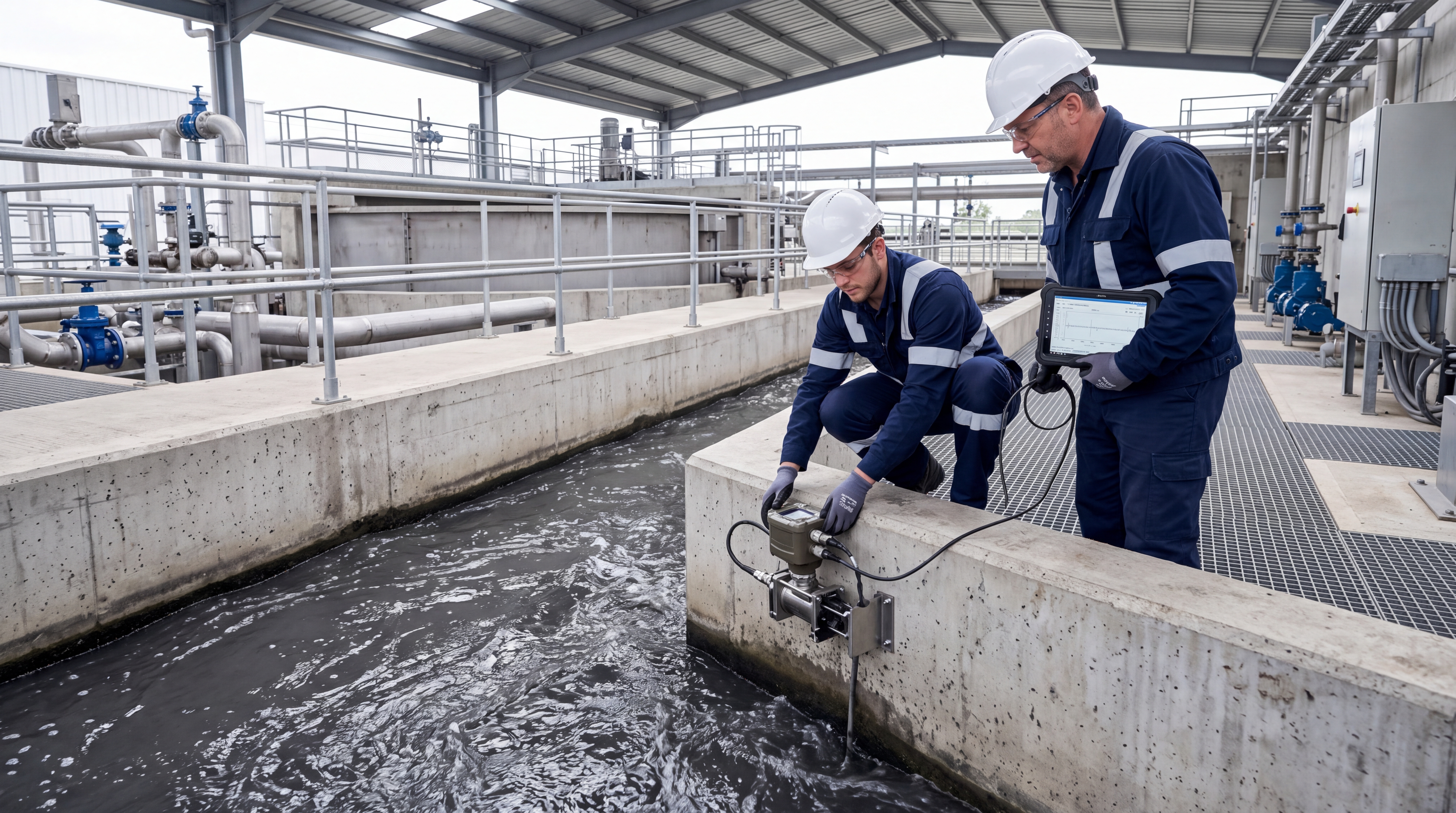
Recently, Yicai Technology has compiled this practical guide aimed at enhancing the continuity and verifiability of flow monitoring data. Focusing on scenarios such as municipal drainage, river water volume monitoring, irrigation district channels, and industrial open channels, the guide addresses key elements including non-contact measurement, flow velocity, water level, and integrated cameras. It provides robust methods for installation, commissioning, maintenance, and troubleshooting.
01 Site Survey & Pre-Installation Preparation
Before installation, a rigorous site survey must be completed to ensure data accuracy. The measurement point should be located in a straight, stable, and regularly shaped channel section.
- Avoid Turbulence: Stay away from sharp bends, drops, weirs, pump station inlets/outlets, and obvious backflow areas.
- Straight Sections: Maintain sufficient upstream and downstream straight sections to minimize the effects of turbulence and transverse flow.
- Channel Condition: If the channel has siltation, weeds, or uneven slope protection, clean it in advance or adjust the installation position.
- Mounting Stability: Ensure the mounting bracket is firm and reliable to prevent vibration and displacement.
- Orientation: The sensor or radar antenna must face the flow direction, with the beam covering the effective water surface while avoiding obstruction by railings, trees, cables, or bank walls.
02 Precise Equipment Installation
Proper installation geometry and electrical safety are critical for long-term stability.
Height & Angle Configuration
Determine mounting height and pitch angle based on the on-site water level variation range. This ensures valid echoes at low water levels and prevents submersion at high water levels.
- Radar Water Level Gauges: Avoid near-field interference.
- Pressure-Type Gauges: Pay attention to the cleanliness of the pressure sensing tube and zero-point setting.
Electrical & Visual Setup: Power and communication lines must be waterproofed, lightning-protected, and properly grounded. Cables should be laid in conduits using waterproof terminals. The integrated camera should be installed to allow clear observation of the water surface, staff gauge, or flow velocity characteristics. Ensure lens orientation avoids strong backlighting, configuring supplementary lighting or sun shields if necessary.
03 System Commissioning & Calibration
The commissioning phase transforms hardware into accurate data. It begins with parameter configuration and verification.
1. Parameter Configuration
Input basic information such as channel cross-section shape, bottom width, side slope, roughness coefficient, or flow velocity correction factor. Set data collection intervals, upload frequencies, and alarm thresholds. For non-contact equipment, verify transmission angles, valid echo strength, and liquid surface recognition logic to avoid misjudgment caused by foam, raindrops, or floating objects.
2. Zero-Point Calibration
Perform water level zero-point calibration by recording the baseline value under static water or known conditions. Compare this reading with a manual staff gauge to ensure accuracy.
3. Flow Velocity Verification
Focus on data stability and rationality. Compare readings on-site using a portable flow meter, the float method, or historical stage-discharge relationships.
Troubleshooting Tip: If flow velocity remains at zero, shows negative values, or is abnormally high, check the installation angle, presence of effective scattering on the water surface, beam obstruction, and parameter settings. Use the integrated camera to visually confirm if water surface fluctuations match the equipment output.
04 Routine Maintenance Schedule
Although non-contact measurement equipment does not directly contact the water body, environmental factors still require regular upkeep.
- Monthly Inspection: Check equipment appearance, bracket tightness, cable connections, and waterproof sealing.
- Increased Frequency: Inspect more often during flood seasons, after heavy rain, or following sudden water level changes.
- Cleaning: Clean dust, moisture, oil stains, or spider webs from the radome, lens, and sensor surfaces. Use soft materials to avoid scratches.
- Debris Removal: Clear silt, weeds, and floating debris near the water level gauge to prevent blockages or false readings.
- Camera Checks: Regularly verify image clarity, timestamps, storage status, and network connectivity to ensure visual data supports verification.
05 Common Faults & Troubleshooting
Address issues systematically based on power supply, signal, parameters, and environment.
Equipment Offline
Check power supply voltage, solar panel status, battery health, and communication module connectivity.
Water Level No Change/Jumps
Check for zero-point drift, sensor obstruction, air bubbles in pressure tubes, or radar near-field interference.
Abnormal Flow Velocity
Verify installation angle, echo quality, cross-section parameters, and water surface conditions (wind, foam, oil).
Frequent Data Fluctuations
Check grounding, lightning protection, cable shielding, and surrounding electromagnetic interference.
Conclusion
The stable operation of Doppler flow meters relies on standardized installation, meticulous commissioning, and continuous operation and maintenance. By standardizing the construction of integrated monitoring stations for water level, flow velocity, and cameras, and establishing comparison calibration and inspection records after commissioning, the credibility and traceability of flow data can be significantly improved. This provides more reliable on-site evidence for drainage dispatch, river and lake supervision, and irrigation district metering.

