Doppler Flowmeter Routine Maintenance and Troubleshooting Manual
In the Era of Non-contact Measurement, Installation, Commissioning, and Maintenance Determine Data Quality.
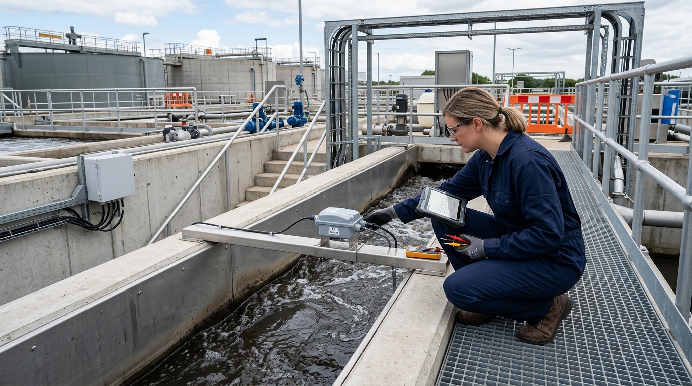
In scenarios such as water measurement in irrigation districts, urban drainage, river ecological flow monitoring, and industrial open-channel metering, Doppler flowmeters are expanding from traditional contact measurement to comprehensive monitoring based on non-contact measurement and multi-sensor fusion. A Doppler flowmeter generally refers to equipment that uses the Doppler shift principle to obtain the velocity of scatterers on the water surface or in the water body, and then calculates flow rate by combining water level and cross-sectional parameters. In new-generation applications, it is often integrated with radar water level gauges, video cameras, and edge computing terminals to form an integrated flow measurement system of “flow velocity + water level + image.”
Compared with contact-type equipment, non-contact measurement does not directly intrude into the flow and is less affected by sewage corrosion, entanglement by floating debris, and sediment impact, making it suitable for complex environments such as drainage outlets, box culverts, channels, and rivers. However, non-contact does not mean “accurate once installed.” Surface ripples, wind waves, reflections, nighttime illumination, installation depression angle, cross-sectional parameters, water level zero point, and flow velocity coefficient calibration all affect final flow results. Especially after integrating camera-assisted flow measurement, image clarity, calibration accuracy, and target recognition stability also become key operation and maintenance focus points.
Objective of This Guide
With field operability as the objective, this article systematically summarizes the installation steps, commissioning methods, routine maintenance, and common troubleshooting of Doppler flowmeters. It also addresses key elements such as non-contact measurement, flow velocity, water level, and integrated cameras, providing specific parameters, checklists, and application cases as references for frontline technical personnel in water affairs, environmental protection, irrigation districts, and municipal drainage.
I Pre-installation Survey: First Clarify the Boundary Conditions
The installation quality of a Doppler flowmeter largely depends on site selection in the early stage. Although non-contact measurement avoids underwater work, it is more sensitive to observation conditions. Before installation, key confirmation should focus on channel morphology, flow regime stability, water surface width, water depth range, flow velocity range, floating debris conditions, power supply and communication conditions, and future maintenance access.
- Flow Measurement Cross-section: Select a location that is straight, regular, and free of abrupt changes. Generally, the upstream straight channel section should be no less than 10 times the water surface width (or 10 meters), and the downstream section no less than 5 times (or 5 meters). Avoid locations such as drops, sharp bends, sluice gates, pump station inlets/outlets, backwater areas, diversion outlets, and obvious sedimentation reaches.
- Water Surface Width & Depth: For radar Doppler or video flow measurement, the water surface width is recommended to be no less than 0.5 meters. Common non-contact systems can accommodate water depths from 0.1 meters to over 5 meters and flow velocities from 0.05 m/s to 10 m/s.
- Scattering Conditions: Doppler velocity measurement relies on scatterers. A mirror-calm water surface may cause weak radar echoes. Conversely, excessive floating debris or foam can create false targets. Artificial roughening or algorithm adjustment may be required.
- Power & Communication: Plan for solar (battery capacity for 3-7 days) or mains power with lightning protection. Ensure signal strength meets data upload needs. Maintain safe inspection access near the installation location.
II Installation Steps: Coordinated Deployment
The installation is not merely fixing a single sensor; it is the coordinated deployment of the velocity measurement unit, water level unit, integrated camera unit, and power/communication unit.
1. Foundation & Pole Construction
Pole height commonly 3–8 meters; equipment center to water surface between 3–6 meters. Verticality deviation < 1‰. Ensure drainage around foundation.
2. Radar/Camera Unit
Face the cross-section directly. Radar depression angle 15°–30°. Camera lens must cover target area avoiding backlight/shadows.
3. Water Level Gauge
Install where surface is calm. Beam directed vertically. Height at least 0.5m above max historical water level. Use stilling wells if fluctuations are large.
4. Cross-section Parameters
Survey bottom width, side slopes, and elevation. Update records if sedimentation/scouring occurs. Align water level zero point with channel bottom.
Steps 5 & 6: Configure power/grounding (Grounding resistance ≤ 4Ω) and complete on-site labeling/safety protection. Archive installation photos for future reference.
III Commissioning Methods: Calibration & Validation
Commissioning determines whether the flowmeter can “measure accurately, transmit stably, and display clearly.” Verify item by item around water level datum, velocity coefficient, cross-section model, and image calibration.
- Power & Communication Check: Verify voltage (9V–36V DC), SIM card/APN settings, and server connection. Check video stream smoothness and timestamp accuracy.
- Cross-section & Water Level Setting: Input channel type, dimensions, and zero points. Compare display with manual measurements; error should be within ±1 cm.
- Velocity Parameter Commissioning: Set the surface velocity coefficient (typically 0.75–0.92). Perform field calibration against standard current meters or ADCP at 3–5 different water levels. Target indication error: ±5% (relaxed to ±10% in complex conditions).
- Integrated Camera Calibration: Establish mapping between pixel coordinates and actual distances using known widths or calibration boards. Disable auto-zoom/EIS during calibration.
- Data Upload & Alarms: Set sampling intervals (1–10 mins routine; 30s–1 min flood season). Configure alarm thresholds for high/low water, missing data, and communication faults.
IV Routine Maintenance: Focus on Lens, Beam, and Datum
"Maintenance workload is lower than contact-type equipment, but not 'maintenance-free.' Long-term operation affects measurement stability due to lens contamination, bracket loosening, or datum changes."
Remote Inspections (Daily/Weekly)
- Check data completeness (>98%).
- Monitor water level/velocity curves for anomalies.
- Verify image quality and timestamps.
On-site Inspections (Monthly)
- Clean lenses/radomes (remove dust, bird droppings).
- Check water level datum and stilling wells.
- Inspect mechanical parts, bolts, and solar panels.
- Record all maintenance activities for traceability.
V Common Fault Troubleshooting
Follow the sequence: Power/Communication → Sensors → Parameters → Environmental Interference.
| Symptom | Possible Causes | Handling Method |
|---|---|---|
| No data / Comm interruption | Power outage, battery aging, SIM arrears, antenna loose. | Check voltage, controller status, signal strength, and grounding. |
| Water level unchanged/jumps | Loose gauge, beam obstruction, stilling well blocked, datum change. | Check verticality, clear obstructions, compare with manual gauge, increase averaging time if windy. |
| Velocity zero/low (Flow exists) | Wrong angle, weak echo, calm water, lens obstruction. | Adjust angle/gain, clean lens, ensure trackable texture for video. |
| Velocity high/fluctuating | Wind waves, vessels, debris, vibration, wrong coeff. | Use video to identify interference, tighten bracket, recalibrate coefficient. |
| Large flow deviation | Sedimentation, shape change, bypass, full-pipe misjudgment. | Re-measure cross-section, verify area calculation, check for backflow. |
| Camera blurry/no image | Dirty lens, fogging, bandwidth low, storage full. | Clean lens, check network bitrate, restart service, adjust exposure/fill light. |
VI Application Cases
Case 1: Irrigation District Main Canal
Scenario: Trapezoidal channel (3m width), normal depth 0.8–1.4m. Installed radar Doppler + camera at 4.5m height, 20° angle.
Result: Initial coefficient 0.90 caused +6% error. Field calibration corrected it to 0.86. Post-correction deviation: -2.8% (low) to +3.5% (high). Data completeness exceeded 99%.
Case 2: Urban Drainage Outlet
Scenario: Box culvert (2m width), rapid rise during rain, heavy debris/foam. Switched from contact to non-contact radar/camera.
Solution: Shrunk video recognition area to avoid bank garbage; added sudden change filtering; adjusted fill light to reduce reflection.
Outcome: Provided continuous data during rapid rises. Managers used images to distinguish garbage blockage from abnormal drainage, improving data credibility.
VII. Outlook: Integrated O&M
The value of Doppler flowmeters lies not only in replacing manual measurement but in providing continuous, traceable data. As technology matures, equipment moves from single sensors to multi-source fusion: radar for stable velocity/water level, cameras for scene verification, and edge algorithms for interference filtering.
Future focus shifts from “whether it can measure” to “whether it measures accurately and stably long-term.” Standardized installation, digital cross-sections, and intelligent O&M platforms will make Doppler flowmeters reliable nodes in irrigation modernization, urban drainage, and ecological supervision.
Yicai Technology believes that as standards and intelligent platforms improve, Doppler flowmeters will provide stable support in increasingly complex water environments.

