Drainage Pipe Network Monitoring: Routine Maintenance and Troubleshooting Manual
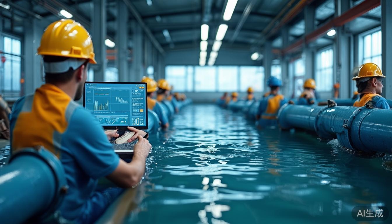
The drainage pipe network is a critical piece of infrastructure in the urban flood-prevention system. With extreme rainfall becoming more frequent, relying solely on manual inspection and post-event response can no longer meet the needs of fine-grained dispatch. Online monitoring data such as water level, flow, drainage capacity, and overflow risk can help managers identify risk points before rainfall, assess backwater, full-pipe conditions, and overflow during rainfall, and review pipe-network bottlenecks after rainfall.
Focusing on practical implementation of drainage pipe network monitoring, this article covers site selection, installation, commissioning, maintenance, and fault troubleshooting, providing actionable references for construction projects, operation and maintenance management, and urban flood prevention.
1. Monitoring Objectives, Site Selection Principles, and System Composition
Drainage pipe network monitoring should primarily target “water-level early warning, flow calculation, flood-prevention dispatch, and operation-and-maintenance diagnosis.” Water level reflects the height of water in the pipe and is the most direct indicator for determining full pipe, overflow, and backwater. Flow reflects the drainage capacity of the network and can be used to verify design standards, assess dredging effectiveness, and evaluate pumping-station operating status. Auxiliary parameters such as manhole-cover tilt, water immersion, and gas can improve operational safety levels.
Monitoring points should cover three categories of locations. First, risk points such as flood-prone areas, underpasses, low-lying road sections, and outlets of aging residential communities should be equipped with level gauges and flow meters. Second, key nodes such as trunk pipes, branch trunk pipe confluences, inlet and outlet ports of retention/storage basins, pumping-station forebays, and inlets of rainwater treatment facilities should be monitored to understand system flow distribution. Third, construction areas, aged and damaged pipe sections, and severely silted pipe sections should be monitored for O&M diagnosis and dredging assessment. It is generally recommended that each flood-prone zone have at least one level point and one flow point, and that trunk pipes have one monitoring point every 500 to 1,000 meters. The specific density should be determined based on catchment area, pipe diameter, slope, design return period, and flooding history.
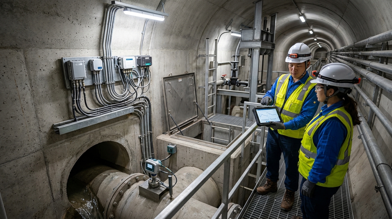
A monitoring system typically consists of sensors, data acquisition terminals, communication modules, a power supply system, and a platform. Level sensors may be radar, ultrasonic, or pressure-type, with common accuracy of ±1 cm or ±0.25% FS. Flow sensors may be Doppler, open-channel, ultrasonic, or electromagnetic, with common accuracy of ±3% to ±10%. The acquisition terminal sampling interval can be set to 1 to 10 minutes; it may be shortened to 1 minute during flood season and set to 10 to 15 minutes during normal periods to balance data volume and device power consumption. The platform should perform basic management of point ledger, threshold configuration, alarm rules, data quality, and interlocked contingency plans.
2. Pre-installation Preparation and Site Survey
Before installation, document verification and a site survey must be completed. Documents include pipe-network CAD or GIS drawings, pipe diameter, slope, design flow, historical flooding points, pumping-station locations, manhole-cover coordinates, ownership entities, and O&M boundaries. The site survey should record manhole depth, manhole opening dimensions, internal structure, pipe diameter, flow condition, silt thickness, water-surface width, whether the pipe is full, and whether floating debris or foam is present, as well as communication signal strength, power supply conditions, traffic environment, and work windows. For underpasses, stormwater box culverts adjacent to rivers, and flood-prone road sections, safe access routes, rescue conditions, nighttime lighting, and flood-season working risks should also be confirmed.
The equipment list usually includes level gauges, flow meters, brackets, expansion bolts, stainless-steel clamps, waterproof aviation connectors, cables, grounding wires, surge protectors, protective boxes, solar panels, rechargeable batteries, acquisition terminals, and tools. Selection must match operating conditions: for sewage networks or networks containing corrosive gases, non-contact radar level gauges are preferred; for points with manhole depth exceeding 8 m and large water-surface fluctuations, pressure-type level gauges with vent-protection devices may be considered; for open channels or regular cross-sections, ultrasonic flow meters or weirs/flumes may be used; for non-full circular pipes, Doppler velocity meters or clamp-on ultrasonic flow meters may be used, but pipe material, wall thickness, and sediment concentration must be confirmed.
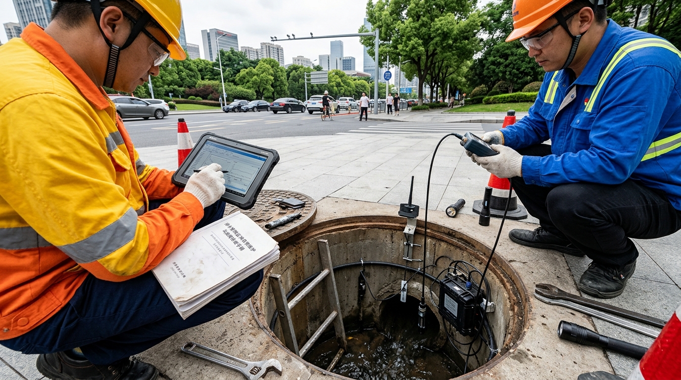
Example: In a certain city, a stormwater box culvert is 1.2 m wide and 1.0 m high, with a normal water level of about 0.35 m and a possible near-full condition during heavy rain. The site survey found weak 4G signal inside the manhole, so a high-gain antenna or a low-power NB-IoT solution should be selected. The bottom of the box culvert has about 5 cm of sediment, requiring adjustable brackets and a regular dredging mechanism. Before installation, a confined-space work plan should also be developed, with gas detection, ventilation, safety harnesses, rescue ropes, and standby attendants prepared to avoid blind manhole entry.
3. Installation Procedures for Level and Flow Monitoring Equipment
Level Gauge Installation Guidelines
When installing radar level gauges, priority should be given to ensuring that the beam is not obstructed. The sensor is generally fixed to the manhole wall or a top bracket, with the antenna center aligned with the water surface and kept perpendicular to it. A margin should be reserved in the measurement range: the lowest water surface should preferably be 10% to 20% above the lower limit of the range, and the highest water surface should preferably be 5% to 10% below the upper limit. In circular pipes, the beam should be kept from hitting the pipe wall, duckweed, foam, or inspection ladders; false measurements can be reduced by adjusting the installation position and angle. For small-diameter pipes, an 80 GHz radar with a smaller beam angle is recommended, typically 3° to 8°, to reduce pipe-wall interference.
When installing ultrasonic level gauges, strong turbulence and large amounts of foam should be avoided. There should be a stable reflecting surface between the sensor face and the water surface. The mounting bracket should be rigidly fixed to prevent displacement caused by wind or vehicle vibration. Because the speed of sound is affected by temperature, the device should have temperature compensation; common operating temperature ranges are -20°C to 70°C. After installation, check whether the probe is clean and whether condensation or biofilm is present; add desiccant or protective covers if necessary.
Pressure-type level gauges calculate water level from hydrostatic pressure and are suitable for scenarios with large manhole depths where non-contact installation is difficult. During installation, the sensor should be lowered to the bottom of the manhole or fixed on a bracket, and the vent hole should be kept clear to compensate for atmospheric pressure changes. If gas, oil, or sediment is present in the manhole, a protective sleeve should be added and cleaned regularly. Pressure-type level gauges are sensitive to zero-point drift; during installation, the initial water level and sensor installation elevation should be recorded to establish the correspondence “sensor elevation—level reading—absolute water level” for subsequent calibration.
All level installations require waterproofing and mechanical protection. Cables should be secured along brackets to avoid hanging or immersion; connectors should use waterproof aviation plugs or potting, with an IP rating preferably no lower than IP68. The acquisition box should be installed near the manhole cover or on a manhole-wall bracket, with an enclosure IP rating no lower than IP65, and grounding and lightning protection should be provided. After installation, a power-on test should be performed, recording readings in three conditions—empty manhole, low water level, and high water level—and comparing them with a manual tape or portable water-level gauge.
Flow Meter Installation Guidelines
Flow monitoring installation depends more heavily on hydraulic conditions than level monitoring. For open channels or regular box culverts, a “level—flow” relationship can be used, meaning flow is estimated from water level. In this case, channel bottom width, side slopes, bed slope, and roughness coefficient must be accurately measured, and a weir/flume or standard cross-section should be installed. The level gauge should be installed in the stable upstream reach, 0.5 to 1.0 m from the weir/flume or contraction section, to avoid downstream backwater effects. During installation, ensure that the sensor reference plane is consistent with the channel-bed elevation, with an error preferably controlled within ±1 cm.
For non-full pipe flow, Doppler velocity meters or ultrasonic flow meters may be used. Doppler sensors are usually fixed to the pipe bottom or side wall to measure velocity and water level, and flow is then calculated using the cross-section geometry. The installation location should avoid elbows, drops, confluences, and disturbed zones downstream of gates. It is recommended that the upstream straight pipe length be at least 3 pipe diameters and the downstream straight pipe length at least 5 pipe diameters. If an ideal straight pipe section cannot be found, the calibration frequency should be increased during commissioning, and the stage-discharge relationship should be corrected. Doppler measurement depends on suspended particles or air bubbles: if sediment concentration is too low, the signal is weak; if it is too high, attenuation may occur. Frequency and installation method should be selected according to actual water quality.
Clamp-on ultrasonic flow meters are suitable for metal or plastic pipes under full-pipe or stable-flow conditions; pipe material, wall thickness, and lining must be confirmed before installation. The sensor mounting surface should be polished and cleaned, coupling agent applied, and the sensors secured with clamps while maintaining a symmetrical sound path. For large-diameter pipes, installation accuracy requirements are higher, and the angular deviation error should be controlled within 1°. Electromagnetic flow meters generally require full pipe and are not suitable for frequent non-full-pipe conditions. If used for sewage lift pipes, grounding, lining, and electrode fouling should be checked carefully.
After flow equipment is installed, dredging and maintenance measures should be established simultaneously. Sensors on the bottom of manholes or pipes are easily covered by sediment and debris; protective covers or deflectors should be provided, and inspection ropes should be reserved. Bracket material is recommended to be 304 or 316 stainless steel, and bolts should be anti-loosening treated. For flood-prone points, flow equipment can be installed together with level equipment to form a triple assessment of “water level—flow—overflow,” improving the reliability of flood-prevention warnings.
4. Acquisition, Communication, Power Supply, and Commissioning/Calibration
The acquisition terminal is responsible for connecting sensors and uploading data. Common interfaces include RS485, analog, digital, and Ethernet. When multiple sensors are connected, independent addresses must be set to avoid bus conflicts. Modbus RTU addresses should be assigned sequentially starting from 1. Between the terminal and the platform, MQTT, HTTP, or industry protocols may be used. During commissioning, each sensor’s address, range, unit, sampling period, and alarm threshold should be recorded to ensure that platform displays are consistent with field conditions.
Communication methods should be selected according to field signal conditions. 4G is suitable for points with large data volume and high response requirements, while NB-IoT is suitable for low-power, low-frequency reporting points. When installing antennas, avoid obstruction by metal manhole covers; keep the antenna away from the manhole wall, and use extension feeders if necessary. During commissioning, signal strength such as RSRP or RSSI should be recorded, and the online rate over 7 consecutive days should be no lower than 95%. If the signal is weak, adjust the antenna position, add an external antenna, or switch to fiber-optic backhaul.
Power supply commonly uses solar panels plus rechargeable batteries. Power consumption estimation includes sensors, acquisition terminals, communication modules, and heating/dehumidification. Assuming an average current of 50 mA, daily energy consumption is about 1.2 Ah; if there are 5 consecutive rainy/cloudy days, about 6 Ah of reserve capacity is needed. Considering depth of discharge and low-temperature attenuation, batteries of 20 to 40 Ah are often selected. Solar panel output is recommended to be no less than 5 W, with orientation and tilt adjusted according to local latitude; the panel surface should not be long-term shaded by leaves or oil. Battery boxes should be ventilated to avoid high temperatures accelerating aging.
Lightning protection and grounding are important for the safety of drainage pipe network monitoring. Surge protection devices (SPDs) should be installed in acquisition boxes, and SPDs may be added to power and communication lines. Grounding resistance is generally required to be no greater than 4 Ω; in difficult areas, equipotential bonding can be implemented using metallic structures inside the manhole. Before the thunderstorm season, grounding connections should be inspected for looseness or oxidation to avoid equipment damage or data interruption caused by lightning strikes.
Commissioning should be carried out in four steps: “hardware power-on—data reading—platform mapping—interlock testing.” After power-on, check whether sensor readings are stable, whether the acquisition terminal can read RS485 data, and whether the platform receives messages. Data units should be unified: for example, level in meters or centimeters, flow in cubic meters per hour or liters per second, and time should be synchronized to Beijing Time to avoid time-zone errors.
Level calibration requires establishing the correspondence between field readings and absolute elevation. A common method is to measure water-surface elevation using a steel tape, portable pressure gauge, or total station, and then compare it with device readings. Generally, 7 consecutive days of manual comparison at least 3 times per day are performed; if the error is controlled within ±2 cm, the system can be considered stable. Pressure-type level gauges should also be checked for zero-point drift; if the empty-manhole reading exceeds ±1 cm, the zero point should be reset. Radar level gauges should be checked for false echoes, which can be confirmed through empty-manhole tests and shielding tests.
Flow calibration is more complex and requires establishing a stage-discharge relationship. For open channels and weirs/flumes, standard formulas may be used, but field verification is mandatory. For non-full pipes, portable current meters, Doppler devices, or manual flow measurements may be used to record flow at different water levels and form an H-Q curve. It is recommended to cover at least three water-level ranges—low, medium, and high—with no fewer than 3 data sets in each range. If the curve-fitting error exceeds 10%, check cross-section measurements, sensor installation location, and downstream backwater.
Alarm thresholds should be set according to flood-prevention objectives. Level warning can be divided into three levels: attention level, warning level, and danger level. For example, if the normal water level of a flood-prone point is 0.30 m, the attention level may be set at 0.50 m, the warning level at 0.70 m, and the danger level at 0.85 m or close to the pipe-crown elevation. Flow thresholds may be set at ±20% of the historical average for the same period, or at 80% of design flow. The platform should support threshold interlocks, such as automatically sending SMS or app messages when the level exceeds the warning level, and linking to pumping-station and gate dispatch plans. During commissioning, simulated triggers should be performed to verify response time; generally, the time from sensor upload to platform alarm should not exceed 3 minutes.
5. Routine Maintenance and Common Fault Troubleshooting
Routine maintenance should follow the principle of “regular during normal periods, intensified during flood season, and review after rain.” During normal periods, inspections can be performed monthly and calibration quarterly; during flood season, inspections can be performed weekly or biweekly; within 24 hours after heavy rain, check for sediment accumulation, water immersion, offline status, and abnormal data. Maintenance tasks include cleaning sensor surfaces, checking bracket bolts, inspecting cable waterproofing, recording battery voltage, cleaning solar panels, verifying platform data integrity, and checking settlement around manhole covers.
Common Fault: Abnormal Level Readings
High readings from radar level gauges are often caused by the beam hitting the pipe wall, floating debris, or foam; low readings are often caused by sensor loosening, incorrect installation height, or water-surface fluctuations.
Ultrasonic level gauges may develop condensation or biofilm causing echo attenuation; pressure-type level gauges may produce errors due to vent-hole blockage, sediment coverage, or zero-point drift. Corrective actions include adjusting installation angle, cleaning probes, recalibrating, replacing desiccant, or adding protective covers.
Common Fault: Abnormal Flow Readings
Symptoms include sudden increases, sudden decreases, or prolonged zeros. Possible causes include sensors covered by sediment, failure of the stage-discharge curve, cross-section siltation, downstream submergence, weak Doppler signal, or communication packet loss.
Troubleshooting: First check if level is normal, then examine velocity, cross-section parameters, and installation location. If level is stable but flow fluctuates, check the velocity sensor and coupling condition; if flow remains persistently low, dredge and recalibrate. For open channels, also check whether weirs/flumes are damaged, deformed, or clogged.
Device offline is the most common problem in operation and maintenance. Priority should be given to checking supply voltage, SIM card status, APN configuration, signal strength, and serial-port address. If voltage is below 3.5 V, the battery may be discharged or the solar panel may be damaged; if signal is weak, check antenna position and feeders; if some sensors are online but the platform has no data, check acquisition-terminal logs and platform interfaces. For jumping data, investigate electromagnetic interference, poor grounding, power fluctuation, and communication packet loss; solutions may include re-grounding, adding filters, or shortening cables.
Maintenance work also requires a ledger. For each monitoring point, record the installation date, equipment model, sensor elevation, reference water level, calibration results, threshold settings, inspection records, fault handling, and replaced parts. For flood-prone points, pumping-station forebays, and retention/storage basin nodes, a special flood-season maintenance checklist should be established to ensure that equipment is online, data are trustworthy, and alarms are reachable before rainfall arrives.
6. Case Application and Acceptance Key Points
A drainage flood-prevention monitoring project in an urban area deployed 20 level points, 8 flow points, 5 pumping-station interlock points, and 1 retention/storage basin node, covering 3 flood-prone zones. The project used radar level gauges to monitor pipe water levels, Doppler flow meters to calculate stormwater-pipe flow, acquisition terminals to upload data via 4G, and a platform configured with three-level water-level thresholds and sudden flow-change thresholds. During commissioning, each point was compared for 7 consecutive days, with level error controlled within ±1.5 cm and flow error controlled within ±8%.
During a heavy-rain event, 1-hour rainfall reached 35 mm. The water level at an underpass rose from 0.38 m to 0.72 m. After the level exceeded the 0.70 m warning threshold, the platform automatically pushed messages and interlocked to close the forebay gate and start the pumping station. Field inspection found a small amount of debris blockage in the pipe section; after the rain, the section was dredged and the stage-discharge curve was updated. This case demonstrates that level, flow, and pumping-station interlocks can improve flood-response efficiency, provided that monitoring points are properly sited, data are accurately calibrated, and thresholds match dispatch plans.
Acceptance should focus on four categories of indicators: first, installation quality, including secure brackets, reliable waterproofing, and compliant grounding; second, data quality, including online rate, completeness rate, error, and alarm response time; third, O&M documentation, including point ledger, calibration records, threshold lists, and emergency response plans; fourth, long-term stability, with at least one flood season recommended. General requirements are an online rate no lower than 95%, data completeness no lower than 98%, level error within ±2 cm, flow error within ±10%, and alarm response time not exceeding 3 minutes.
7. Outlook: From Single-Point Monitoring to System Diagnosis
In the future, drainage pipe network monitoring will evolve from single-point alarms to system diagnosis. Level and flow data will be integrated with rainfall forecasts, pipe-network hydraulic models, pumping-station dispatch, manhole-cover status, and video surveillance to form a digital twin for urban waterlogging. AI can be used to identify data anomalies, predict overflow risk, assess dredging effectiveness, and assist in generating dispatch recommendations.
For O&M personnel, practical priorities remain standardized installation, precise calibration, and continuous maintenance. Only when the physical conditions, data quality, and response procedures of every monitoring point are solidly implemented can drainage pipe network monitoring deliver real value in flood prevention and routine operation and maintenance.