Complete Guide to Installation and Commissioning of Irrigation District Informatization
Including Common FAQs: Shifting from Device Stacking to a Full-Process System That Is Maintainable, Measurable, and Water-Saving.
Introduction: The Paradigm Shift in Irrigation Management
In recent years, informatization of irrigation districts has been shifting from single-point equipment installation and simple data collection to an integrated operation system centered on smart irrigation, water-saving management, water measurement and metering, and informatization platforms. For agricultural water users, irrigation district managers, water conservancy metering personnel, and frontline O&M staff, what truly determines project success is not the number of devices, but whether on-site installation is standardized, whether commissioning forms a closed loop, whether maintenance is sustainable, and whether faults can be rapidly located.
Especially in irrigation district scenarios with complex canal systems, limited power and communication conditions, and dispersed management personnel, informatization systems must be able to "see the data, manage the devices, calculate water accounts clearly, and reduce costs."
This guide focuses on the key nodes from construction to operation of irrigation district informatization projects, systematically reviewing installation steps, commissioning methods, routine maintenance, and common fault troubleshooting. Note that parameters mentioned are common industry configurations; specific projects should be adjusted according to water source conditions, canal morphology, crop irrigation systems, network coverage, and management permissions.
I. Preliminary Preparation and System Design
Before launching an irrigation district informatization project, the first step is to complete requirement clarification and on-site survey. The survey should cover water source intakes, main canals, branch canals, distributary canals, farm canals, terminal canals, field plots, drainage ditches, sluice gates, pumping stations, power distribution rooms, communication base stations, roads, and power supply conditions. It is generally recommended to deploy water measurement and control nodes according to a four-level system of "main canal–branch canal–distributary canal–field."
Medium District Config
- Main Canals: 2–5 points
- Branch Canals: 10–30 nodes
- Distributary/Terminal: 50–200 nodes
Core Indicators
- Metering: Level, Flow, Volume
- Control: Gates, Valves, Pumps
- Platform: Latency, Retention
Accuracy Targets
- Water Level: ±1 cm
- Flow Error: ±2% – ±5%
- Gate Resolution: ≥1%
Communication scheme selection should adapt to local conditions. Nodes close to management stations with available power can use 4G/5G or industrial Ethernet; remote canal sections can use LoRa, NB-IoT, BeiDou short messages, or low-power wireless. Power supply schemes can use grid power, solar panels plus batteries, wind-solar hybrid, or low-power battery solutions. For conventional solar power, it is recommended to configure PV panels of no less than 60 W to 120 W and batteries of 100 Ah to 200 Ah. Lightning protection and grounding are easily overlooked but extremely critical; outdoor equipment grounding resistance is generally required to be no greater than 4 Ω.
II. On-Site Installation Steps: Ten Key Actions
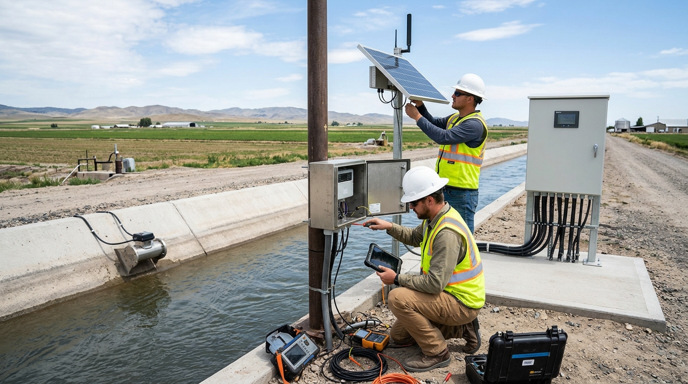
Foundation Construction
Avoid scour areas. Concrete dimensions typically 800×800×1000 mm. Depth below frozen soil line. Strength grade ≥ C25.
Rack and Cabinet Installation
Outdoor rating ≥ IP65. Solar panels oriented south (or optimal azimuth) with tilt angle ≈ latitude (±5°).
Water Level Sensor Installation
Radar meters perpendicular to surface. Ultrasonic avoid foam/algae. Pressure types need sealed vents. Range: Main 2–5m, Terminal 0.5–2m.
Flowmeter Installation
Check cross-sections. Electromagnetic flowmeters require full pipe, 5D upstream / 2D downstream straight pipes. Select DN based on velocity range.
Gate and Control Equipment
Verify stroke, limits, torque. Install filters for solenoid valves. Control boxes need local/remote switching and emergency stop.
Power and Grounding
Use charge/discharge controllers for solar. Battery temp -10°C to 50°C. Ground wire ≥ 16 mm². Separate signal and power lines.
Communication Modules
Elevate antennas. LoRa gain 3–8 dBi. Record IMEI, ICCID, APN, server address. Support bidirectional status readback.
Cable Laying and Labeling
Use conduit. Reserve slack. Weather-resistant materials. Labels at both ends with ID, signal type, destination.
Device Numbering and Ledger
Unique IDs (e.g., GQ-DR-01-Z-008-2026). Record model, location, elevation, accuracy, comms method, dates, and spare parts.
Pre-Acceptance Self-Inspection
Check verticality, sealing, orientation, waterproofing, grounding, voltage, signal strength, and platform online status.
III. Commissioning Methods: Single Points to Closed-Loop
Commissioning should follow the sequence of "single-device commissioning – single-node joint commissioning – zone system joint commissioning – platform closed-loop verification." Avoid testing many devices simultaneously at the beginning.
Key Performance Metrics for Acceptance
- Data Completeness Rate: ≥ 95%
- Communication Success Rate: ≥ 98%
- Critical Control Command Success Rate: ≥ 99%
- Page Response Time: ≤ 3 seconds (Normal Scenario)
- Data Ingestion Delay: ≤ 5 minutes
During zone system joint commissioning, simulate real water allocation. Conduct 30–60 minutes of continuous conveyance at branch nodes. Compare upstream inflow, gate opening, and downstream levels. Use portable flowmeters or standard containers for cross-checking (at least 3–5 times). If deviation exceeds 5%, recheck cross-section or flume dimensions.
After commissioning, prepare a report including device lists, test data, deviations, rectification items, and acceptance conclusions. Attach photos, wiring diagrams, and comparison records. Retain at least 7 days of continuous operation data for water measurement nodes and 3 complete irrigation datasets for smart irrigation nodes.
IV. Routine Maintenance: Cycles and Data Governance
Inspection Tier System
- Daily: Platform duty (Online rate, alarms)
- Weekly: Zone O&M (Voltage, signal spot checks)
- Monthly: Patrol (Sealing, solar cleaning, grounding)
- Quarterly: Calibration (Level, flow, opening)
- Annual: Verification (Trade settlement compliance)
Critical Spare Parts
Configure 5%–10% of device quantity. Replaceable within 24 hours.
- 4G/LoRa Modules & Antennas
- Solar Controllers & Batteries
- Radar/Ultrasonic Sensors
- Relays & Waterproof Connectors
Battery Life: Lead-acid lasts 3–5 years at 25°C (shorter in heat); Lithium requires strict BMS. Monitor panel output current; if consistently low, check shading or controller parameters.
Data Governance: Establish unified coding rules. Standardize fields (timestamp, ID, level, flow, etc.). Set validation rules: e.g., trigger review if water level changes > 5 cm/min. Retain historical data for at least 3 years; archive important metering data for 5+ years.
V. Common Fault Troubleshooting
| Fault Type | Primary Causes | Troubleshooting Sequence |
|---|---|---|
| Offline / No Upload | SIM overdue, antenna loose, server port change, power failure. | Check voltage → Indicator lights → SIM status → Server config → Handheld log reading. |
| Data Jumps / Static | Beam obstruction, sediment adhesion, cable break, parsing error. | Compare with staff gauge → Check sensor cleanliness → Verify platform parsing vs field reading. |
| Large Flow Error | Non-full pipe, bubbles, scaling, wrong diameter setting, unstable flow. | Confirm operating conditions → Check straight pipe length → Re-calibrate coefficient before replacing hardware. |
| Gate Not Actuating | Command not issued, control power off, limit protection, mechanical jam. | Check feedback status → Test manual/electric switch → Inspect torque/current limits → Lubricate lead screws. |
| Solar Restart | Continuous rain, shaded panels, aging battery, excessive load. | Measure panel V/I → Check battery capacity → Reduce night sampling frequency → Verify controller params. |
| Lightning Damage | Poor grounding, missing surge protectors, shield gaps. | Do not just replace modules. Improve grounding resistance (<4Ω), add signal isolation, check equipotential bonding. |
VI. Case Reference: Quantified Results
A medium-sized irrigation district (300,000 mu) renovated its system with 120 water measurement nodes (6 main, 28 branch, 52 distributary, 34 field). Using radar/ultrasonic sensors, 4G/LoRa comms, and hybrid power, the project achieved significant results after one year:
Disputes decreased by 40%, and average fault recovery time shortened from >24 hours to <6 hours. Initial issues with solar shading and lack of status feedback were resolved by increasing PV capacity and adding opening feedback loops, highlighting the importance of continuous O&M.
VII. Outlook: From Metering to Dispatching
Future irrigation district informatization will evolve toward "calculating water accounts, optimizing allocation, controlling processes, and evaluating water savings." Technologies like edge computing, digital twins, and AI anomaly recognition will further integrate. However, stable field devices and credible data remain the foundation.
Recommendations for Management Units
- Standardize Construction Manuals: Incorporate installation, commissioning, and ledgers into institutional systems.
- Cultivate Hybrid Talent: Train personnel who understand both hydraulic structures and IT/communication systems.
- Prioritize Data Quality: Use accuracy, online rates, and completeness as core assessment indicators.

