Non-contact radar level meters are now the default choice for reservoir water-level monitoring, replacing submersible pressure transducers and float encoders at new dam installations. The appeal is obvious: no wetted parts, immunity to sedimentation and biofouling, and a service life decoupled from water quality. Yet reservoir sites are not simply "bigger river sites" — they impose a distinct set of environmental constraints that, if ignored, show up later as data dropouts, spurious echoes and fried telemetry units.
The Four Reservoir-Specific Constraints
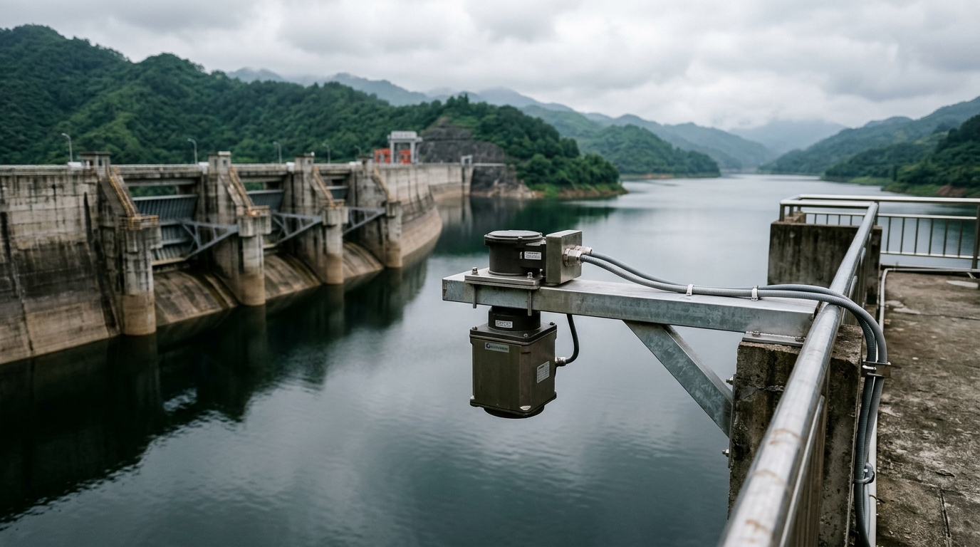
Long range and beam footprint. An FMCW radar with an 8° beam antenna illuminates a footprint roughly 5.6 m across at a 40 m mounting height. On open water this is harmless — arguably beneficial, since the footprint averages out wavelets. The risk appears near spillway guide walls, intake towers and stilling basins, where a wide beam can pick up multipath reflections from concrete surfaces. Keep a clear 45° cone beneath the antenna free of vertical structures, or narrow the beam and accept a higher wave-lock loss rate.
Wind waves. An open reservoir generates 20–40 cm waves in Beaufort 5 conditions. Vertical incidence at 80 GHz keeps specular reflection loss low, and on-instrument averaging plus median filtering typically suppresses wave-induced scatter to within ±1 cm. Very narrow beams (3°–5°) look attractive on paper but lose lock more often on tilted wave faces; 5°–8° is the practical sweet spot for reservoir duty.
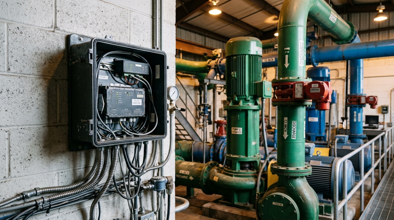
Lightning exposure. A dam-crest radar mast is frequently the highest conductive point for hundreds of metres and sits in an attractive position for side flashes. The dominant failure mode is not a direct strike but inducted surges travelling along power and signal cables into the telemetry RTU. Specify a three-stage defence: an independent earth electrode for the antenna bracket (earthing resistance ≤4 Ω, per IEC 62305 practice), surge protective devices on every conductor entering the cabinet, and equipotential bonding inside the RTU enclosure.
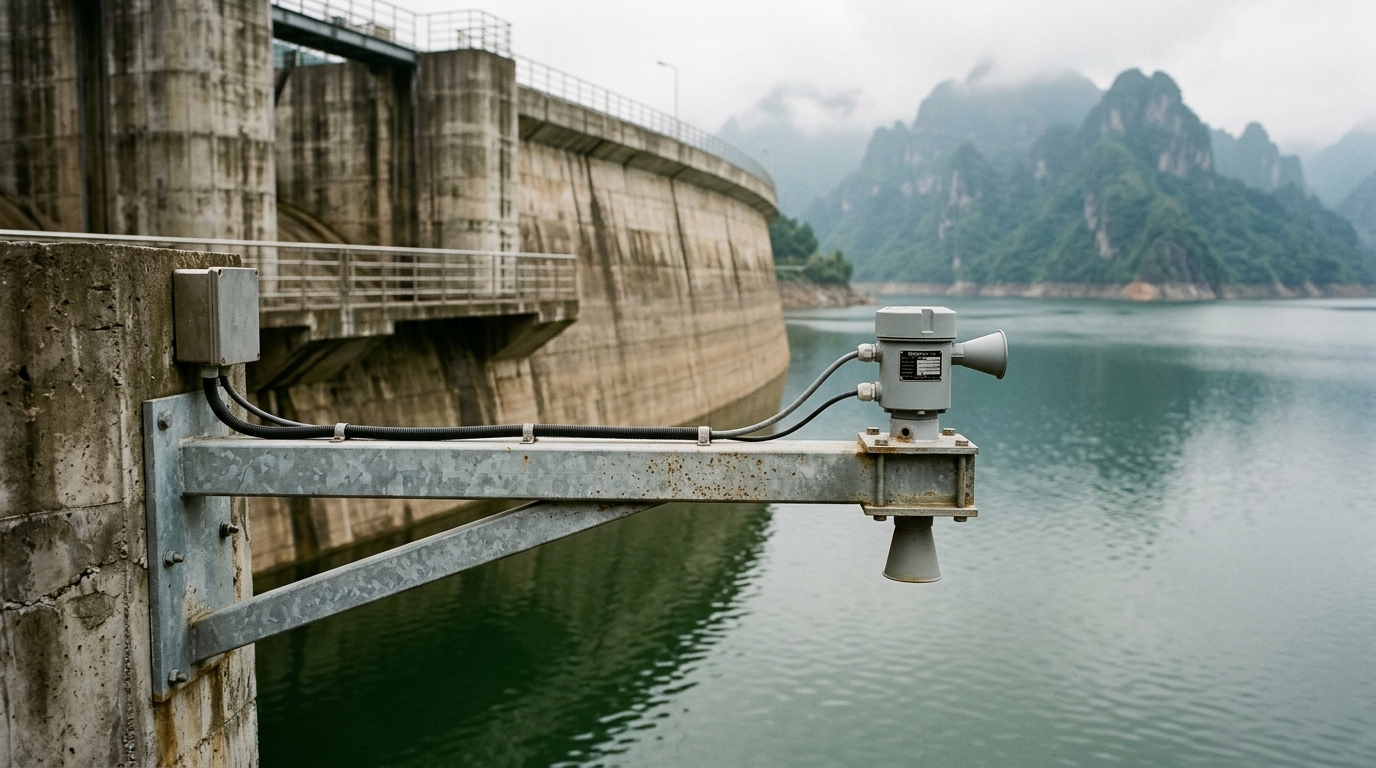
Condensation and biological fouling. Large diurnal temperature swings over water bodies deposit dew on flat lens antennas; winter frost and bird droppings attenuate transmission and can generate false near-field echoes. Choose hydrophobic-coated lens antennas or self-heating variants (≤5 W, comfortably covered by a solar supply), and position the bracket so the antenna is not a convenient perch.
Quantified Selection Criteria
- Band and range: 80 GHz FMCW; select a range class at least 20% above maximum pool level — a 40 m range for a 30 m dam.
- Accuracy: ±1 mm to ±5 mm static accuracy far exceeds hydrological requirements (reservoir gauging tolerances are of the order of ±2 cm); spend the budget on environmental robustness instead.
- Protection class: IP68 enclosure, −30 to 70 °C operating range, wind resistance ≥40 m/s for exposed dam crests.
- Interfaces: RS-485 Modbus-RTU plus 4–20 mA analogue output gives integrators redundancy when connecting to a hydrological IoT RTU.
Commissioning Checklist
Mount the sensor on a cantilevered bracket on the crest, at least 20 m clear of intake vortices and spillway turbulence. During commissioning, complete three tasks: (1) air-gap calibration — verify the mounting height against a laser rangefinder; an error above 2 cm must be corrected in the instrument zero point; (2) 24-hour wave observation — log raw echo strength and reading variance, and widen the averaging window if scatter exceeds ±3 cm; (3) comparison against a staff gauge — at least five synchronised readings, with 95% of deviations within ±2 cm after bias correction. For the first two weeks after handover, check daily data completeness remotely, and watch for a fixed offset appearing at dawn during the condensation season.
Takeaway
Reliability at reservoir sites is multiplicative: sound selection × disciplined installation × complete lightning protection × rigorous commissioning. Missing any single factor degrades long-term data quality. Integrators should codify the checklist above into a site-level work instruction and pair each gauge with a solar-powered IoT RTU for low-touch operation.