Background: Why rivers are the hardest environment for level sensing
Unlike the calm surface of a reservoir, a natural river exhibits persistent waves, turbulence and floating debris. During flood events, flow velocities of 3–5 m/s can mechanically destroy contact-type instruments. Non-contact radar level meters operating at 80 GHz or 26 GHz have therefore become the default choice for river gauging stations. In practice, most field failures are not caused by the sensor itself but by three engineering factors: mounting position, height budget and signal-processing configuration.
Mounting position and height engineering
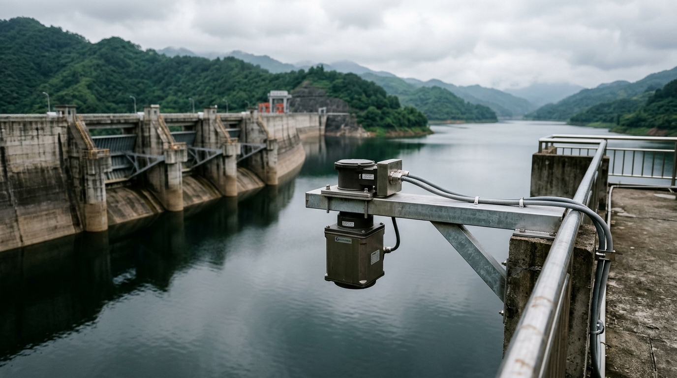
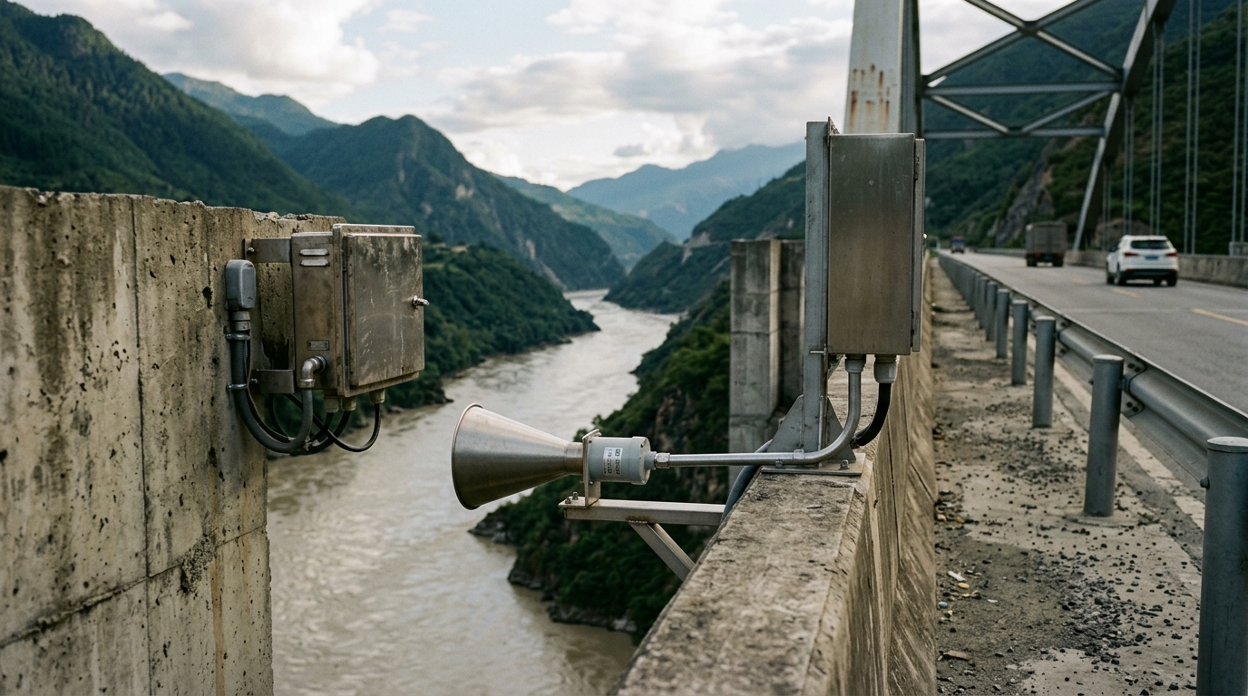
- Avoid pier-induced turbulence: mount the sensor on a cantilever bracket at least 1.5 m away from bridge piers to stay clear of the local surface bulge created by pier wakes.
- Height budget: set the minimum mounting height at the historic highest flood level plus a 1.0 m safety margin. For a standard 30 m range instrument, the useful band is typically 5–25 m; readings inside the 0.3–0.5 m near-field blanking zone must be discarded.
- Beam angle vs. footprint: an 8° beam antenna produces a footprint of roughly 1.4 m diameter at 10 m height. If piers or boulders fall inside that footprint, echo SNR collapses — choose a 3° narrow-beam antenna instead.
- Bracket stiffness: heavy truck crossings excite bridge decks with ±2–3 mm amplitude at 2–10 Hz. Design the bracket's natural frequency outside this band, otherwise the level series shows periodic oscillation.
Echo processing and commissioning strategy
Turbulent river surfaces generate numerous spurious echoes. Commission in three steps. Step 1: inspect the raw echo curve and verify that the true water-surface return leads reflections from the deck and railings by at least 10 dB. Step 2: configure the tracking window to lock onto the first significant echo and enable median filtering over ≥8 samples to suppress wave peaks. Step 3: calibrate the zero offset against a staff gauge under calm, low-flow conditions; residual error should stay within ±3 mm, consistent with Class 1 accuracy requirements for hydrological telemetry systems.
Recommended architecture for unattended stations
Combine the radar level meter with an IoT RTU and solar power supply. Provide dual communication paths — LTE as primary and a satellite short-message service as backup — because cellular networks congest during flood events. Sample every 15 min in normal conditions and automatically tighten to 5 min in flood season. Keep the grounding resistance ≤4 Ω and bond all metallic bridge fittings to the instrument enclosure for surge protection (IEC 62305 principles).
Summary
Selecting a radar level meter for river monitoring is not about chasing datasheet accuracy; it is about matching mounting height, beam angle and filtering parameters to the hydrological character of the site. Following the engineering checklist above, non-contact radar delivers continuous, reliable water-level telemetry through flood season — a data backbone for smart water management and urban lifeline protection.