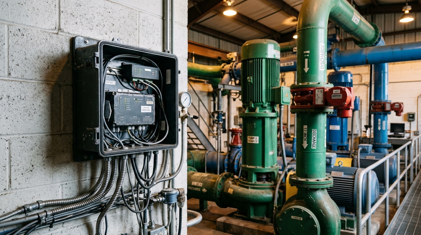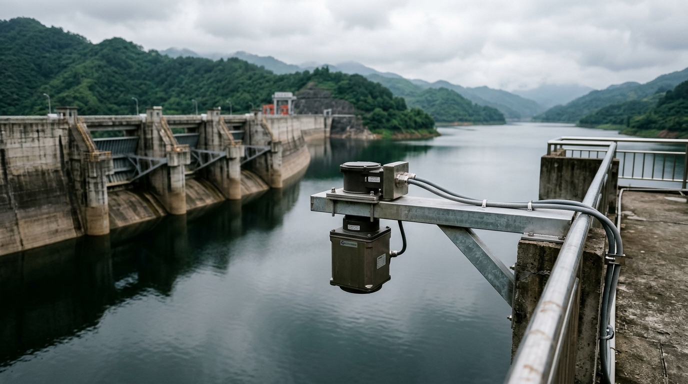
Radar level meters are rapidly replacing ultrasonic and hydrostatic sensors in sewer networks, driven by their non-contact measurement principle and low maintenance burden. Yet the sewer environment is arguably the harshest duty in level measurement: manholes 600–1000 mm in diameter, persistent near-saturation humidity, hydrogen sulfide accumulation, turbulent flow with foam and wall deposits. Field experience shows that most measurement failures stem not from the instrument itself but from siting and commissioning errors. This article summarises the engineering essentials.
Frequency Selection: Prefer 80 GHz Narrow-Beam Units
A typical inspection chamber offers very little clearance. Ladders, cables and rough concrete walls all generate spurious reflections. A 26 GHz radar with an 8°–10° beam angle covers more than 0.5 m of beam footprint at a 3 m range — wide enough to hit the chamber wall or ladder. An 80 GHz FMCW unit narrows the beam to roughly 3°–4°, keeping the footprint under 0.2 m and allowing the antenna to fire straight down through the cover opening. For pipes below DN1000 and narrow flumes, 80 GHz should be the default choice; 26 GHz or lower frequencies only make economic sense in open detention basins and pump-station forebays.
Industrial radar level meters are typically specified at ±3–5 mm accuracy, but achievable accuracy in a sewer depends on installation quality. For acceptance testing, run a parallel comparison against a staff gauge or submerged pressure transmitter for at least 24 hours, and require deviations within ±10 mm.
Installation: Three Pitfalls to Avoid
1. Stay away from inflow turbulence. Locate the measuring point in a hydraulically smooth reach, at least 3–5 pipe diameters downstream of drop structures or junction tees. Where surface velocity exceeds 3 m/s, standing waves and rolling whitewater cause severe echo fluctuation — use a stilling well or baffle plate if unavoidable.
2. Manage mounting height and range margin. Keep 0.3–0.5 m of clearance between the antenna and the highest expected level to avoid the near-field dead zone. Remember that in circular pipes the level changes extremely fast near full-bore condition, so sampling intervals of 5 minutes or less are needed to capture surcharge events.
3. Guard against condensation and corrosion. Day–night temperature swings make condensation on the antenna window the leading cause of drift. Select models with an air-purge port or a hydrophobic antenna coating. Enclosures should be 316L stainless steel or engineering plastic, rated IP68 per IEC 60529, and cable entries must include drip loops. In high-H₂S chambers, prefer antennas sealed integrally with the housing so gas cannot creep along seams to corrode the electronics.
Commissioning: False-Echo Suppression Is Not Optional
After installation, always run a false-echo learning procedure at low water level so the radar records and masks reflections from fixed obstructions such as ladders and pipe intrusions. Most "jumping level" complaints in the field trace back to this step being skipped, or to the masking curve failing to cover the ladder position.
Set a damping time of 10–30 s and an appropriate echo-strength threshold to reject weak returns from foam and floating debris. For units with temperature compensation, verify that the compensation curve matches the actual temperature swing inside the chamber. Finally, cross-validate radar readings against the IoT RTU telemetry and upstream flow data to rule out systematic bias before trial operation begins.
Summary
Success with radar level meters in sewers is 30% selection and 70% installation and commissioning. Narrow-beam 80 GHz solves the confined-space problem, disciplined siting avoids flow-induced noise, and false-echo learning plus anti-condensation design determine long-term stability. Freeze these points into a commissioning checklist and close each item before sign-off — that is how non-contact measurement delivers on its maintenance-free promise in urban drainage monitoring.