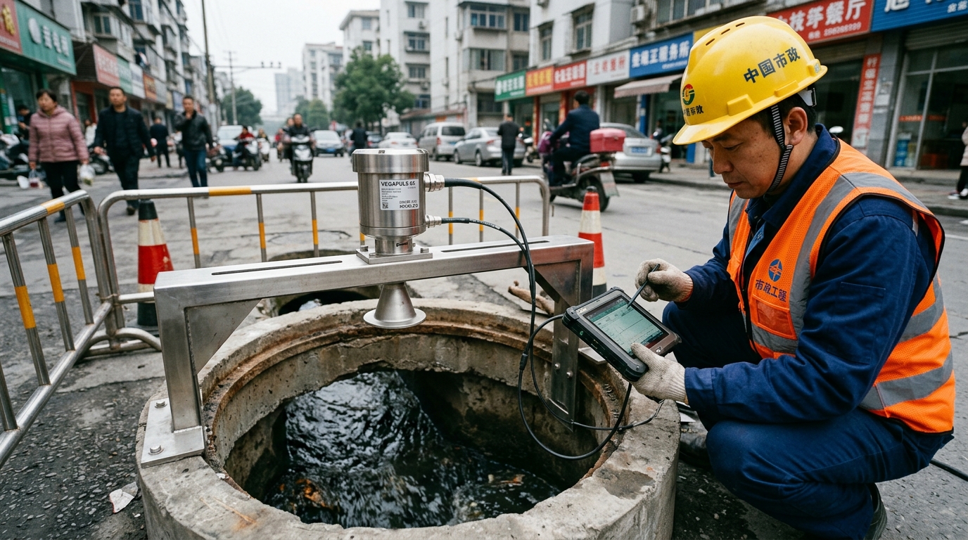
Municipal sewer manholes are the most exposed nodes of urban drainage monitoring networks — and among the harshest environments for any level sensor. Permanent condensation, accumulation of H₂S and methane, full submersion during storm overflows, and strong multipath reflections from manhole walls and benching all degrade measurement reliability. For engineers specifying non-contact radar level meters in these conditions, three decisions dominate long-term data quality: frequency band, ingress protection, and commissioning discipline.
1. Selection: Three Non-Negotiable Specifications
Beam width and frequency. Typical manholes are only 0.7–1.2 m in diameter. A 26 GHz radar with an 8–12° beam already illuminates a footprint wider than 0.7 m at 5 m mounting height, so wall echoes compete with — or overwhelm — the surface return. An 80 GHz FMCW radar narrows the beam to under 3°, keeping the footprint below 0.3 m and geometrically decoupling the measurement from wall reflections. For sewer duty, 80 GHz is the default choice.
Ingress and chemical resistance. Specify IP68 per IEC 60529 with an explicitly stated continuous immersion depth and duration — not the 30-minute laboratory test condition. During overflow events the antenna can remain submerged for hours. The lens should be PTFE or PEEK, and the housing 316L stainless steel or glass-filled engineering polymer, to withstand H₂S attack on metals and elastomer seals.
Dead band and range. Sewer monitoring ranges are typically 0.5–8 m, but the near-field dead band (5–30 cm depending on design) becomes critical in dry weather, when the water surface may fall inside it. Require a dead band of ≤10 cm, or compensate via the invert elevation so that low-flow readings remain continuous.
2. Installation: Avoiding Three Interference Sources
- Keep clear of the influent drop zone. The beam must not be aimed at the point where tributary flow plunges into the channel; turbulent, aerated water drastically reduces signal-to-noise ratio. Mount over the downstream channel or on a side bracket, with the beam axis offset at least 0.3 m from the influent centreline.
- Bracket stiffness and verticality. Use a stainless-steel cantilever bracket and verify beam-axis verticality to within 1° with a digital inclinometer. Off-axis beams require cosine correction and increase the wall-reflection component.
- Cabling and hazardous-area compliance. Route shielded twisted-pair cable through a sealed manhole entry. Where methane may reach 25% of the lower explosive limit, select intrinsically safe (Ex ia) or flameproof (Ex d) equipment certified to the IEC 60079 series.
3. Commissioning: False-Echo Suppression and Two-Point Calibration
Commissioning must include an on-site false-echo learning pass: with the manhole empty or at low level, record the fixed interference profile from walls, step irons and benching into the instrument's suppression map. Then perform a two-point verification — measure the air distance to the water surface with a steel tape and compare it against the instrument reading (tolerance ≤±2 mm), and repeat the comparison before and after a wet-weather event to confirm linearity. Enable both 4–20 mA analogue output (to the local PLC or IoT RTU) and RS485 Modbus-RTU (to the telemetry unit), and configure a plausibility filter rejecting jumps larger than 0.5 m within one minute to keep bubble- and debris-induced spikes out of the SCADA platform.
4. Takeaway
In sewer environments the challenge is not measuring once — it is measuring reliably for years. An 80 GHz narrow-beam radar, IP68 continuous-immersion rating and a PTFE corrosion-resistant lens form the specification baseline; correct mounting geometry eliminates multipath and turbulence errors; and disciplined false-echo mapping plus two-point calibration locks in accuracy. Projects following this path routinely sustain annual data completeness above 98%, providing a dependable foundation for drainage network modelling and urban waterlogging early warning.