Practical Guide for RTU Telemetry Terminals: Water Management Monitoring Applications Using the Hero V9 as an Example
With the continuous advancement of digital water management monitoring projects, the role of RTU telemetry terminals in on-site data collection, protocol conversion, and remote transmission is becoming increasingly prominent. Taking the Hero V9 as an example, such devices are commonly used in monitoring scenarios including water level, rainfall, flow rate, gate position, and pump station status.
To improve project construction and operations and maintenance efficiency, this article summarizes the key operational points across four phases: installation, commissioning, maintenance, and troubleshooting.
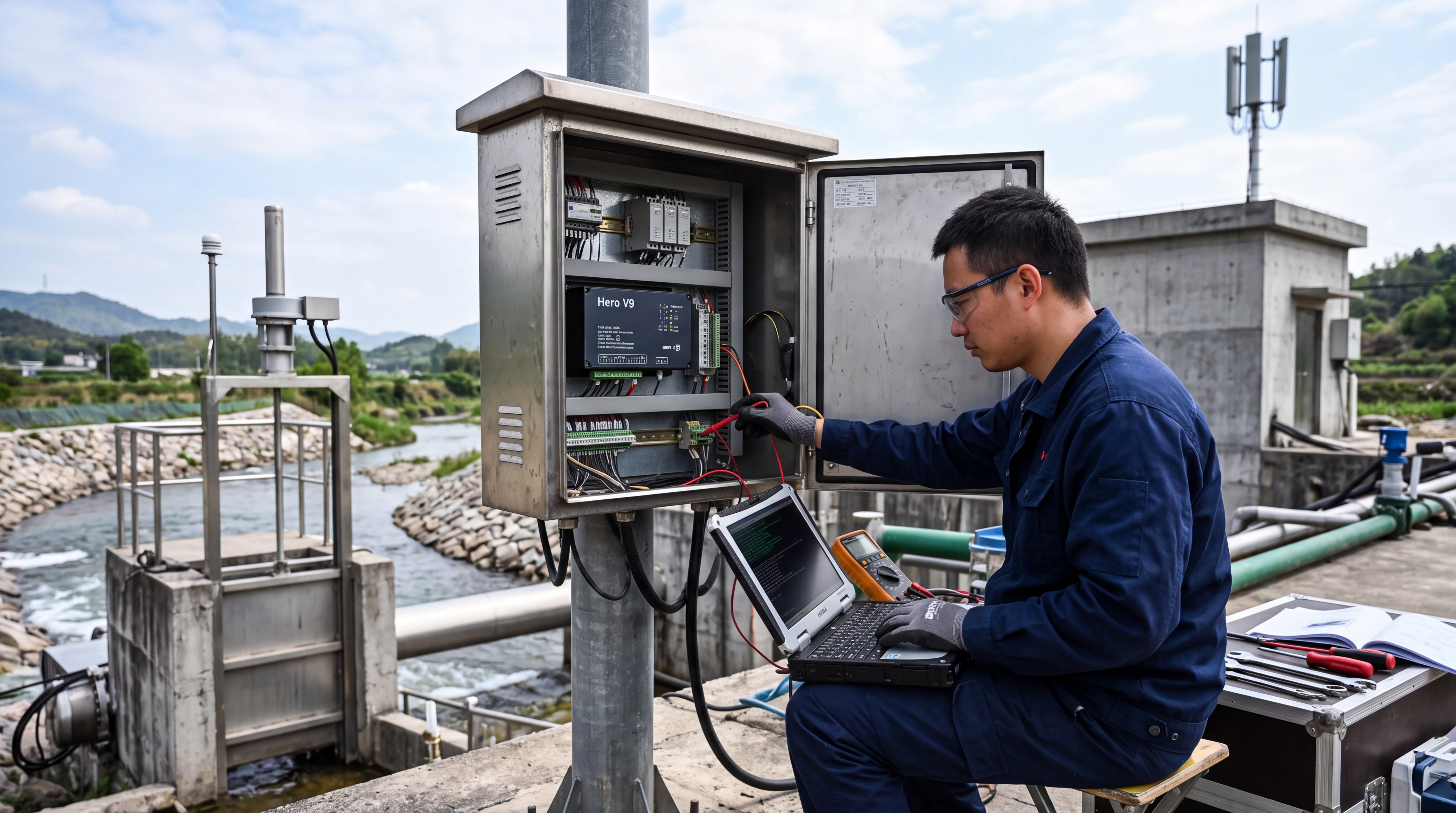
1 Installation: Preparation and Execution
Pre-Installation Verification
Before installation, site conditions and equipment configuration must be verified first. Project personnel need to confirm whether the power supply method, communication module, and number of interfaces of the Hero V9 meet the access requirements, and check whether the sensor types and signal outputs are compatible.
Tip: Water management sites are predominantly located outdoors; therefore, it is recommended to plan the mounting poles, enclosures, lightning protection, grounding, and wiring routes in advance. For low-lying, humid, or lightning-prone areas, the IP rating, antenna mounting height, and power protection measures should be carefully evaluated.
Wiring Sequence
During installation, it is recommended to follow the sequence of "secure first, wire second, and power on last". First, install the RTU inside a sturdy enclosure or control cabinet to avoid the impact of vibration and water accumulation. Next, complete the connections for the power cable, antenna, sensor signal cables, and grounding wire.
- RS485 Bus: Pay strict attention to the A and B polarity.
- Analog Signals: Use shielded cables and ground them locally to prevent interference.
- Final Check: After wiring, ensure terminals are securely fastened, there is no risk of short circuits or loose connections, and no water ingress paths exist before powering on.
2 Commissioning: Data Accuracy and Stability
Initial Configuration
The core of the commissioning phase is to ensure accurate data acquisition and stable remote transmission. After the Hero V9 is powered on, first observe the status of the power and communication indicator lights to confirm that the device has started up normally. Then, enter the configuration interface to set the device address, sampling interval, sensor measurement range, communication parameters, and destination platform address.
Modbus Sensors
Test the register address, baud rate, and data format individually to ensure protocol compatibility.
Analog Signals
For water level and flow rate sensors, calibrate against actual on-site values to ensure measurement accuracy.
Data Link Verification
After completing parameter configuration, cross-verification is required in three ways: viewing real-time data locally, checking platform reception records, and reviewing message logs. Focus on checking whether key data such as water level and rainfall are continuous, whether the units of measurement are correct, and whether the timestamps are accurate.
If the platform displays abnormalities, prioritize checking the communication parameters, APN, or server port configuration, followed by checking the antenna signal strength and SIM card status. Remote transmission commissioning should be retested at different times of the day to observe the impact of network fluctuations.
3 Routine Maintenance Strategy
Routine maintenance should establish a periodic inspection mechanism. It is recommended to check the enclosure sealing, wiring terminals, antenna mounting, and supply voltage once a month; the inspection frequency can be increased during the flood season or critical operational periods.
Key Maintenance Points
- Solar Power Systems: Pay attention to photovoltaic panel cleaning, battery voltage, and charge/discharge status.
- Front-end Sensors: Clear mud, weeds, and dust from water level gauges and rain gauges promptly to prevent measurement errors.
- Documentation: After each maintenance session, record equipment status and parameter changes to form a traceable log.
4 Common Faults and Troubleshooting
Fault Categorization
Common faults can be categorized into four types: power supply, communication, data acquisition, and data integrity.
| Fault Type | Symptoms | Troubleshooting Steps |
|---|---|---|
| Power Supply | Device unresponsive | Measure input voltage, check fuse and power module output. |
| Communication | Connection interrupted | Check SIM card, antenna, signal strength, APN, server address, and firewall policies. |
| Data Acquisition | Missing data or sudden jumps | Troubleshoot sensor power, signal cable shielding, range settings, and filtering parameters. |
| System Wide | Multiple sensors abnormal | Check common power supply, bus wiring, and RTU interface configuration. |
On-Site Handling Methodology
When handling faults on-site, it is recommended to use the substitution method and the sectional troubleshooting method. First, determine whether the problem lies with the sensor, the wiring, the RTU, or the platform side. You can disconnect certain sensors to observe whether the device returns to normal, or replace the communication module, antenna, or power supply for verification.
Warning: If the device experiences repeated restarts, interface damage, or signs of lightning strikes, it should be taken out of service immediately and technical support should be contacted to prevent the fault from expanding.
Conclusion
Overall, the stable operation of RTU telemetry terminals relies on standardized installation, meticulous commissioning, and continuous maintenance. In water management scenarios, terminal devices such as the Hero V9 provide foundational support for hydrological monitoring, scheduling management, and early warning dissemination through data collection and remote transmission.
Project personnel should formulate standardized operating procedures tailored to the site environment, and improve configuration backups and inspection records, thereby enhancing system availability and reducing subsequent operations and maintenance costs.

