Non-contact Measurement vs. Flow Velocity: A Selection Guide for Smart Water Management Scenarios
In water resources metering, urban drainage, industrial process control, and ecological and environmental monitoring, Doppler flow meters are evolving from standalone velocity-measuring devices into field sensing nodes that integrate flow velocity, water level, non-contact measurement, and integrated camera systems. Industry editors have observed that users are no longer primarily focused on "whether the Doppler principle is adopted," but on the representativeness, stability, installation convenience, and data traceability of different technical approaches under real operating conditions.
I. The Technical Essence of Doppler Flow Meters
The core physical basis of Doppler flow meters is to transmit acoustic, electromagnetic, or optical waves and then receive echoes scattered back by particles, bubbles, floating objects, or surface textures in the water, converting frequency changes into target motion velocity. The typical acoustic Doppler relationship can be approximated as a function of frequency shift, flow velocity, incident angle, and speed of sound; when the flow velocity is low, scatterer concentration is insufficient, or the installation angle deviates significantly, signal quality degrades markedly. Therefore, a Doppler flow meter first measures velocity, rather than directly outputting volumetric flow rate.
In open channels, river channels, and drainage box culverts, volumetric flow rate is usually equal to the wetted cross-sectional area multiplied by the cross-section-averaged velocity. The area must be determined jointly by water level, channel-bottom elevation, side slopes, or pipe internal diameter; the average velocity must be obtained through profile velocity measurement, surface velocity conversion, or multi-point velocity fusion. If only surface velocity is measured without establishing a correction relationship to the cross-section-averaged velocity, the final flow-rate error is often amplified.
Scatterer conditions are a key boundary for Doppler velocity measurement. Clear water, low sediment content, low bubble content, or surfaces without floating objects may lead to weak echoes, velocity jumps, or missing data. Conversely, higher sediment content, small bubbles, or stable surface textures make the signal easier to capture. Common engineering factors such as sediment concentration, gas content, particle size, and surface roughness all affect the usability and accuracy of Doppler flow meters.
II. Comparison of Mainstream Technical Approaches
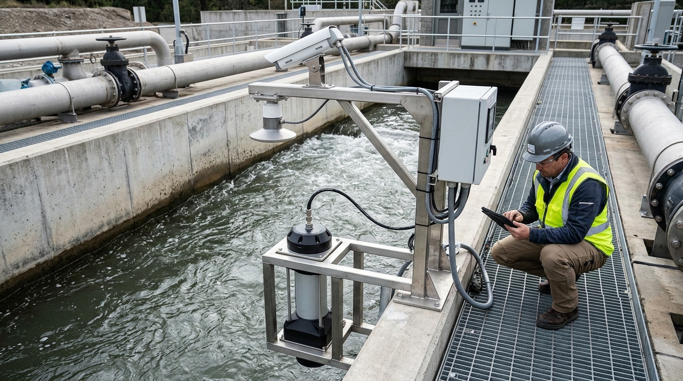
Contact Acoustic Doppler
Typically immerses the probe in water to obtain velocity profiles via multi-beam transmission. Ranges: ~0.03–6 m/s. Accuracy: ~0.01 m/s or 1%. Pros: Directly reflects underwater velocity distribution. Cons: Susceptible to fouling, impacts, and limited maintenance space.
Non-Contact Surface Doppler
Includes radar, laser, and acoustic solutions measuring from bridge sides or pipe tops. Ranges: ~0.05–10 m/s. Accuracy: 0.02–0.05 m/s order. Pros: No medium contact, safer maintenance. Cons: Requires empirical coefficients (0.85–0.95) to convert surface velocity to mean velocity.
Video & Optical Methods
Uses PIV or optical flow tracking on surface textures. Requirements: >30 fps, stable illumination. Accuracy: 0.05–0.1 m/s range. Pros: Good for event monitoring/integrated cameras. Cons: Poor performance at night, rain/fog, or oil-covered surfaces.
Electromagnetic & Transit-Time
Electromagnetic: Needs conductivity >5 µS/cm, accuracy 0.5–1%, sensitive to bubbles/fouling. Ultrasonic Transit-time: Best for clean/low-gas liquids, accuracy 1–2%. Doppler: More adaptable to particles/bubbles but depends heavily on scatterers.
III. Field Value of Non-Contact Measurement
The primary value of non-contact measurement is reducing field construction and operation and maintenance risks. In urban drainage outlets, hazardous industrial media, temporary flood-season monitoring, or existing pipe gallery retrofits, stopping flow, drilling, entering manholes, or contacting sewage creates cost and safety pressure. Non-contact solutions can be installed externally, shortening deployment time and facilitating subsequent replacement and calibration.
However, non-contact measurement does not mean "no field conditions are required." Surface velocity is significantly affected by wind, rain, oil, bubbles, floating objects, and illumination.
- Error Sources: Wind fields change surface velocity; oil and foam weaken radar/video textures; low nighttime illumination affects recognition; pipe-wall vibration destabilizes coupling.
- Installation Parameters: Radar/laser devices are sensitive to incident angles (15–60 degrees). Too large or too small reduces effective range or increases uncertainty.
- Mature Practice: Establish a closed loop of "velocity—water level—cross section—correction coefficient." Use multi-point placement and long-term calibration to reduce single-point representativeness issues.
IV. Synergy of Velocity and Water Level
Water level is a key input for Doppler flow meters to achieve accurate flow-rate calculation. In open channels and partially full pipelines, water-level errors are directly converted into wetted-area errors. Common methods include pressure-based (mm-level accuracy, density-sensitive), radar-based (non-contact, good for sewage), ultrasonic (temperature/vapor sensitive), and camera-recognition (staff gauge reading).
Example Calculation:
In a rectangular channel with 1.2m depth, a 1cm water-level error causes ~0.8–1.2% area error. Combined with a 5% velocity error, total flow-rate error approaches 6%. This highlights that water-level accuracy is the basis of flow-rate credibility.
Cross-section-averaged velocity cannot be simply equated to single-point velocity. Contact profile Doppler reconstructs distribution; non-contact surface Doppler estimates mean velocity via correction coefficients. Long-term operation requires establishing water-level–area–velocity coefficient curves, which must be periodically reviewed due to sedimentation, vegetation growth, or structural changes.
V. Integrated Cameras: From Surveillance to Sensing
Integrated cameras are becoming an important supplement to Doppler flow meters. Modern video flow measurement extracts surface velocity from continuous frames using particle image velocimetry and deep learning. It is suitable for scenarios with rich surface features like rivers and weirs. When combined with Doppler, the field obtains not only velocity but also traceable visual evidence.
- Hardware Requirements: 1080P/4K resolution, >30 fps, wide-angle/varifocal lenses, IR/white-light illumination, IP67/IP68 protection, edge-computing units.
- Algorithm Limitations: Accuracy drops significantly under nighttime, heavy rain, strong reflection, or low-texture water surfaces. Not recommended as a sole high-accuracy trade-metering method.
- Fusion Benefits: Doppler provides velocity profiles; cameras recognize floating objects, overflow, and personnel intrusion. Edge computing links these for local decisions and remote reporting.
VI. Selection Recommendations
1. Rivers & Large Open Channels
If contact installation is permitted, use Acoustic Doppler Profile Velocity + Radar/Pressure Water Level. Error controlled to 3–5%. If access is unsafe, use Bridge-side Non-contact Doppler, but strictly establish surface-to-mean velocity correction relationships.
2. Urban Drainage & Box Culverts
Combine Non-contact Surface Doppler with Integrated Cameras. Reduces O&M costs in complex media. Acceptable error for early warning is 5–8%; discharge metering requires stricter calibration.
3. Industrial Pipelines
Return to medium characteristics. Clean/conductive -> Electromagnetic. Clean/low-gas -> Ultrasonic Transit-time. Particles/Bubbles/External-only -> Clamp-on Doppler. Note: Clamp-on requires stable coupling; consider lifecycle costs for abrasive slurries.
4. Emergency Monitoring
Prioritize speed and coverage. Boat-mounted ADCP for cross-sections; Bridge-side radar for rapid deployment; Drones for post-disaster surveys. Focus on integration with command systems rather than single-instrument accuracy.
VII. Case Observations
Urban Inland-River Governance
Width ~28m, Depth 0.8–2.2m. Used contact acoustic Doppler (15 layers) + radar water level + cameras. Result: Flow-rate error ~4.2%. Camera module provided intuitive evidence for floating objects and overflow alarms.
Wastewater Treatment Plant Influent
Medium contained 2–5% bubbles/solids. Initial non-contact setup had ~9% error. Switched to contact acoustic Doppler with anti-impact probes. Result: Error reduced to ~3.5%, though maintenance increased. Illustrates the balance between convenience and accuracy.
Chemical DN200 Slurry Pipeline
8% solids, temperature variation. Replaced electromagnetic (high wear) with clamp-on Doppler + fixed brackets/temp compensation. Result: Accuracy ~3%. Required regular checks of probe pressure and coupling agent due to vibration/coating changes.
Flash-Flood Warning Cross-Section
Bridge-side non-contact radar + low-light cameras. Completed acquisition within 30 seconds during heavy rain. Result: Automatically triggered snapshots/alarms. Demonstrates clear advantage in response speed for brief emergency events.
VIII. Outlook: Integrated Sensing & Standardized O&M
Future development will evolve toward integrated sensing. Flow velocity, water level, pressure, temperature, cameras, and edge alarms will be integrated into the same field node. Non-contact measurement lowers deployment thresholds, while contact profile velocity serves as the high-accuracy reference. These routes will coexist rather than replace each other.
Standardization and metrological traceability are critical. Correction coefficients, cross-sectional area curves, and test conditions require clearer engineering specifications. Digital twins and platform-based O&M will link Doppler velocity, water levels, and video frames with model forecasting and dispatch decisions.
Final Summary: The Five Key Questions
Selection should revolve around answering these questions clearly:
- Does the medium contain sufficient scatterers?
- Is velocity measurement surface-based or profile-based?
- Are water level and cross-section geometry stable?
- Is contact installation permitted at the site?
- Is the final use early warning, process control, discharge metering, or trade settlement?
Only when these are answered can selection move from a competition of device parameters to a competition of engineering systems. What the industry needs is a calibratable, maintainable, traceable, and interoperable flow-sensing system.

