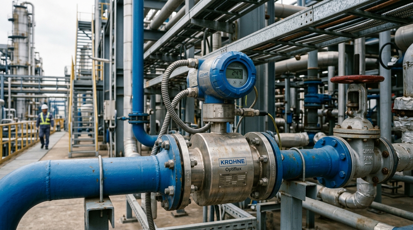
In chemical and fine-chemical plants, process fluids are frequently far less conductive than municipal water: deionised water, organic solvents and some dilute acids or bases may exhibit conductivity of only a few μS/cm. Although the induced voltage in a magnetic flow meter is theoretically independent of conductivity, low-conductivity service raises the source impedance of the electrode–fluid interface and dramatically amplifies noise. This is one of the most common root causes of "unstable readings" in chemical metering.
1. The Signal-Chain Bottleneck at Low Conductivity
A magnetic flow meter applies Faraday's law of induction: the induced voltage E = B·D·v, where B is magnetic flux density, D the tube diameter and v the mean flow velocity. The voltage itself does not depend on conductivity, but the electrode–fluid junction behaves as a high-impedance source. Below roughly 20 μS/cm, source impedance can reach tens of megohms, making the signal vulnerable to amplifier input bias current, cable distributed capacitance and mains-frequency common-mode interference — manifesting as jitter and zero drift.
Mitigations concentrate at the front end of the signal chain:
- High-input-impedance preamplifier — input impedance on the order of 1012 Ω with low-bias-current amplifiers to limit signal attenuation.
- Excitation strategy — low-frequency pulsed DC excitation suppresses electrode polarisation and stabilises zero; dual-frequency excitation balances low noise against fast response. For high-purity fluids below ~5 μS/cm, a capacitively-coupled (non-contact electrode) magmeter is preferred, since the electrodes never touch the fluid and the interface-impedance problem is eliminated at its source.
- Short signal cables — longer cables increase distributed capacitance; low-conductivity installations should minimise cable runs and use proper shielding.
2. Hazardous-Area Certification and Loop Budgeting
Chemical units are typically explosive-gas atmospheres classified into Zone 0/1/2 under the IEC 60079 series (ATEX in Europe). An integral transmitter must carry a certificate matching the zone: flameproof Ex d IIC T6 or intrinsically safe Ex ia IIC. When an IS loop is used, the safety barrier (Zener or galvanic isolator) must match the instrument parameters, and the distributed capacitance and inductance of the field cable must be verified against the certified loop limits — otherwise the intrinsic-safety rating is void. At commissioning, check three items: the Ex certificate number, the temperature class (T1–T6) and the gas group (IIA/IIB/IIC).
3. Grounding Rings and Equipotential Bonding
Low-conductivity fluids are more sensitive to common-mode interference, so the measuring tube, grounding rings and fluid must be held at a common potential. Install grounding rings directly against the flanges at both ends of a metal pipe; for plastic or lined pipes use grounding electrodes or a three-electrode design. The signal-cable shield should be grounded at a single point (normally the transmitter end) to prevent ground loops, and routes should avoid running parallel to VFDs and high-current power cables.
4. Selection and Installation Guidance
- Conductivity < 5 μS/cm: prefer a capacitive magmeter, or evaluate Coriolis / ultrasonic principles.
- 5–20 μS/cm: choose a low-conductivity-specific model with a high-input-impedance transmitter, dual-frequency excitation and short cabling.
- Straight runs: typically 5D upstream and 3D downstream as a starting point, following the upstream/downstream disturbance rationale reflected in ISO 4064 and OIML R49; avoid pump outlets and sharp bends.
- Enable empty-tube / partial-fill detection — batch charging in chemical plants frequently leaves the line unfilled, and dry-run mis-metering must be avoided.
Conclusion
Reliable metering of low-conductivity chemical fluids is fundamentally a signal-chain problem — from the high-impedance preamplifier and excitation strategy to equipotential grounding, the weakest link sets the error budget. Treat the measured fluid conductivity, the hazardous-area classification and the pipe material as hard selection inputs, combine them with correct straight-run lengths and grounding practice, and the meter can hold ±0.5% accuracy for custody transfer and process control.