Proper Operating Procedures for Electromagnetic Flowmeters under Complex Operating Conditions
A practical guide for DN50 electromagnetic flowmeters in anti-corrosion applications, focusing on installation, commissioning, and maintenance.
Introduction
Electromagnetic flowmeters operate based on Faraday's law of electromagnetic induction and are suitable for measuring the volumetric flow rate of conductive liquids with a certain level of electrical conductivity. For applications such as water treatment, chemical blending, cleaning lines, circulating water, and chemical dosing, the DN50 size is widely used due to its suitability for small to medium flow pipelines.
Calculated based on a DN50 internal diameter of approximately 50 mm, when the flow velocity in the pipe is 1 m/s, the theoretical volumetric flow rate is about 7.07 m³/h; if the flow velocity is controlled within the common range of 0.3 to 5 m/s, the corresponding flow rate is approximately 2.1 to 35.3 m³/h. Therefore, DN50 electromagnetic flowmeters are frequently used in small to medium flow conditions such as 6 to 25 m³/h and 10 to 30 m³/h.
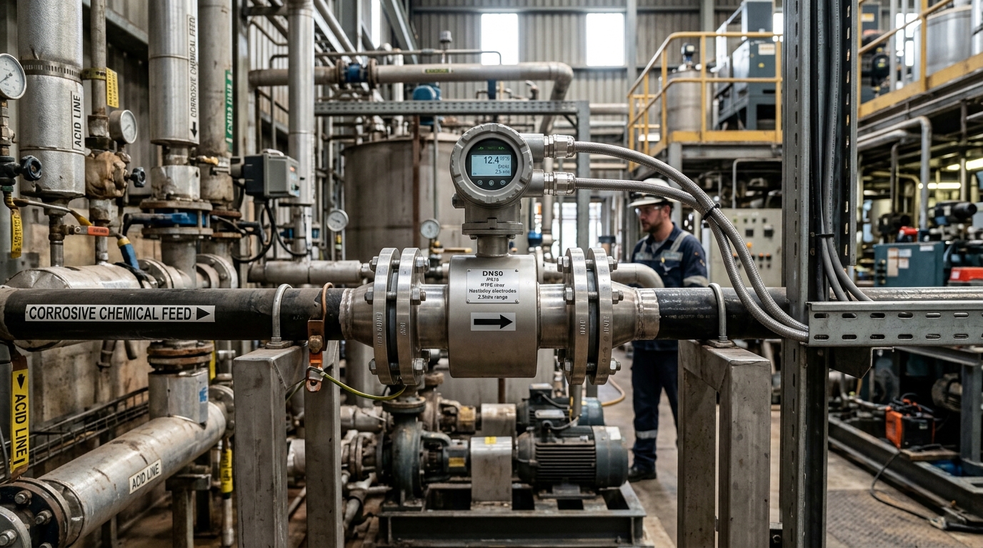
Note on Anti-Corrosion: In corrosive media or humid environments, the long-term stability of the instrument depends not only on the accuracy of the transmitter but also on the anti-corrosion design of the measuring tube, liner, electrodes, housing, and wiring structure. Recent solutions utilize LGF-PA66 injection-molded integrated structures to reduce splicing gaps and lower the risk of moisture ingress.
Pre-Installation Confirmation
Pre-installation confirmation is often more critical than the on-site construction itself. Engineers must verify several key parameters before proceeding:
Medium Properties
- Conductivity must be ≥ 5 µS/cm.
- Check for acids, alkalis, salts, particles, or fibers.
- Evaluate scaling tendency and bubble generation risks.
Temperature & Pressure
- Economic flow velocity: 0.5 – 5 m/s.
- Confirm flange rating if pressure ≥ 0.6 MPa.
- Verify LGF-PA66 temperature resistance if > 60°C.
Anti-Corrosion Matching: For weak acids/alkalis and salt solutions, use compatible liners and electrodes. The LGF-PA66 injection-molded integrated structure improves protection consistency but requires verification against specific medium compositions.
Unboxing Inspection: Check DN50 flange sealing surfaces for flatness, liners for scratches/cracks, and electrodes for cleanliness. Verify nameplate data (size, range, voltage, IP rating). For split-type meters, ensure signal cable length meets specifications to avoid attenuation.
Installation Steps
Proper installation ensures stable measurement and extends the lifespan of the device. Follow these six critical steps:
- Select Location: Avoid direct sunlight, severe vibration, and strong electromagnetic interference. Ensure sufficient disassembly space for maintenance.
- Ensure Straight Run: Maintain at least 5D upstream (approx. 250mm for DN50) and 3D downstream. If elbows or valves are upstream, increase upstream straight run to 10D (approx. 500mm).
- Flow Direction & Orientation: Align the sensor arrow with flow. For horizontal pipes, keep electrode axis horizontal to prevent bubble accumulation (top) or sediment coverage (bottom). Vertical installation should flow bottom-to-top.
- Full Pipe Operation: The meter must measure under full pipe conditions. Avoid gas accumulation points; install exhaust valves if necessary. Place control valves downstream to reduce turbulence.
- Flange Tightening: Use matching gaskets that do not protrude into the pipe. Tighten bolts diagonally in stages to avoid uneven stress on the liner. Perform a pressure test after installation.
- Grounding: Poor grounding causes fluctuations. For plastic pipes, install a grounding ring. Grounding resistance should be ≤ 10 ohms. Keep ground wires short and separate from power cables.
Electrical Wiring & Commissioning
Before wiring, confirm the power supply matches the nameplate (24V DC or 220V AC). Use shielded cables for split-type instruments, grounding the shield at one end. Keep signal and power cables separated by at least 30 cm.
Key Parameter Settings
- DN50 Size & Units: Confirm sensor serial number matches nameplate. Set units to m³/h or L/min.
- Span Setting: Set upper span slightly above max expected flow (e.g., 25 m³/h for a max of 22 m³/h).
- Damping Time: Start with 3–5 seconds. Adjust based on pump pulsation or bubble presence.
- Small Signal Cut-off: Set to 1–3% of span to suppress zero-point noise without affecting low-flow measurement.
Zero Calibration & Empty Pipe Alarm
Zero Calibration: Must be performed under full-pipe, static, no-flow conditions. Wait 5–10 minutes for stabilization before executing. Re-check zero after 24 hours and 72 hours for critical points.
Empty Pipe Alarm: Set thresholds based on medium conductivity (e.g., 600–1000 µS/cm). Do not disable this alarm; it protects electrodes and indicates pipeline abnormalities. Troubleshoot false alarms by checking for bubbles, liquid levels, or electrode scaling first.
Daily Maintenance & Troubleshooting
Maintenance Cycle
- Daily/Weekly: Check flow readings, output current, and alarms via control system.
- Monthly: Inspect appearance, junction box sealing, cable sheaths, and flange leakage.
- Quarterly: Check grounding connection, zero drift, and parameter settings.
- Semi-Annually: Inspect electrodes and measuring tube inner wall for scaling/wear.
- Annually: Comprehensive insulation check and measurement comparison.
Common Faults
- No Display: Check power polarity, fuses, and waterproof seals.
- Zero/Low Reading: Check flow direction, electrode contamination, or low conductivity.
- Fluctuations: Caused by bubbles, partial filling, poor grounding, or pump pulsation. Increase damping time.
- Zero Drift: Often due to process changes, valve leakage, or temperature-induced conductivity shifts.
- Leakage: Check bolt tightening uniformity and gasket aging.
"The goal of maintenance is not to replace the instrument after it fails, but to eliminate faults in the early stages through periodic inspections and trend records."
Application Case Study
Scenario: A reclaimed water reuse station replaced a corroding metal rotameter with a DN50 electromagnetic flowmeter.
- Conditions: Conductivity 650–900 µS/cm, Temp 35–45°C, Flow 8–22 m³/h.
- Solution: DN50 meter with LGF-PA66 injection-molded integrated housing for moisture resistance. Grounding rings installed due to plastic piping sections.
- Result: Initial fluctuations (±6%) were resolved by adjusting valve openings and cleaning biofilm from electrodes. Stability improved to ±0.5%. Zero drift remained below 0.2% after 12 months.
Conclusion
The reliable operation of DN50 electromagnetic flowmeters in complex conditions relies on a closed loop of proper selection, standardized installation, precise commissioning, and proactive maintenance. While advanced materials like LGF-PA66 enhance corrosion resistance, site-specific verification remains essential. By adhering to these procedures—ensuring full pipe flow, robust grounding, and regular electrode cleaning—engineers can achieve stable, accurate metering for water treatment and chemical dosing applications.

