Electromagnetic Flowmeter Daily Maintenance and Troubleshooting Manual
A comprehensive guide for field engineers focusing on DN50 electromagnetic flowmeters, covering installation, commissioning, routine maintenance, and fault troubleshooting in industrial applications.
Introduction: Field Value of DN50 Electromagnetic Flowmeters
In process industries such as chemical, water treatment, pharmaceutical, food, and metallurgy, DN50 electromagnetic flowmeters are commonly used for instantaneous and cumulative flow measurement of conductive liquids in small and medium pipe diameters. Their principle is based on Faraday’s law of electromagnetic induction: when a conductive liquid cuts through a magnetic field, an induced voltage is generated, and the voltage magnitude is proportional to the average flow velocity.
In actual field operation, what really affects accuracy and stability is often not the principle itself, but installation location, grounding quality, full-pipe condition, lining and electrode materials, corrosion-resistant structure of the terminal box, and routine maintenance records.
This guide uses DN50 as a typical nominal diameter and combines keywords such as LGF-PA66, injection-molded integrated, and corrosion protection to form an actionable checklist for field engineers.
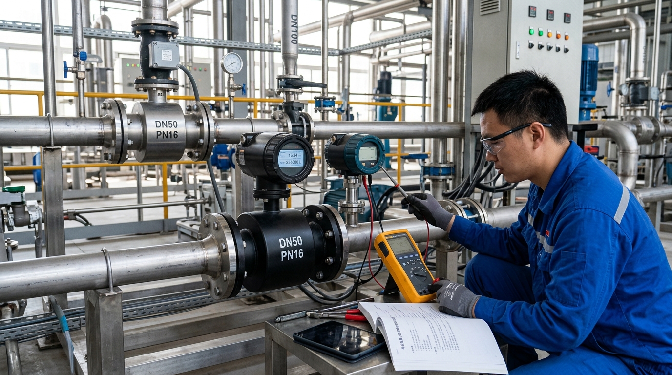
For new projects, medium, conductivity, temperature, pressure, flow velocity range, flange standard, grounding method, and protection rating should be clarified during selection. For retrofit projects, key review items include pipe material, lining integrity, grounding resistance, compatibility with original pipe diameter, and whether there are interference sources such as variable frequency drives, pump pulsation, and valve throttling.
1. Pre-installation Confirmation: Medium, Pipe Diameter, and Material Conditions
Flow Velocity and Conductivity Requirements
Pre-installation should translate process conditions into instrument parameters. DN50 nominal diameter is 50 mm; applicable flow velocity is generally 0.5–10 m/s, with engineering recommendation 1–4 m/s. With internal diameter 0.05 m, cross-sectional area is about 1.963×10^-3 m². Flow velocity 1 m/s corresponds to about 7.07 m³/h, 2.5 m/s about 17.7 m³/h, 5 m/s about 35.3 m³/h. If maximum flow rate long-term exceeds 30 m³/h, evaluate electrode erosion, noise, and pressure loss; if long-term below 0.5 m/s, pay attention to deposition, zero drift, and low-flow cutoff settings.
Medium conductivity determines whether measurement is possible. Usually conductivity greater than 5 μS/cm is required; recommended not less than 20 μS/cm; for stable measurement preferably greater than 100 μS/cm.
Material Selection for Corrosive Media
- Rubber lining: Suitable for general water and weak corrosive liquids.
- PTFE or PFA: Suitable for strong acids and alkalis, high temperature, and complex chemical media.
- Electrodes: May be 316L, Hastelloy C-276, titanium, tantalum, etc., judged according to chemical compatibility charts.
Temperature, Pressure, and Protection Rating
DN50 flanges commonly PN16 or PN25. If medium temperature exceeds 80 °C, rubber lining may be limited; PTFE/PFA should be prioritized. If negative pressure, water hammer, or pump shutdown backflow exists, pay attention to lining resistance to negative pressure. For outdoor installation, terminal box protection rating generally not less than IP65; if water accumulation, spray, or salt spray possible, consider IP67 and add protective cover. For corrosive environments, some field installations use LGF-PA66 injection-molded integrated terminal box or housing structural parts to reduce metal inserts and corrosion paths at seams, but material temperature resistance, chemical resistance, and UV aging conditions must be verified.
2. Installation Steps: From Pipe Preparation to Grounding Loop Closure
Step 1: Pipe Preparation
DN50 electromagnetic flowmeter should be installed on straight pipe as much as possible; conventional requirements upstream at least 5 pipe diameters, downstream at least 3 pipe diameters, i.e. upstream about 250 mm, downstream about 150 mm. If upstream has elbows, tees, reducers, valves, or pump outlets, increase upstream straight pipe to 10D, about 500 mm or more. Pipe inner wall should remove welding slag, burrs, floating rust, cement chunks to avoid scratching lining. Before installation, purge or pressure test; sensor not in service should be removed or isolated during pressure test to prevent high-pressure impact on lining.
Step 2: Direction and Full Pipe
For horizontal installation, the electrode axis should remain horizontal to avoid one electrode being long-term at the pipe top. If the medium contains bubbles, bubbles covering electrodes can cause output fluctuations or empty-pipe false alarms. For vertical installation, flow from bottom to top is recommended to keep the sensor full; top-to-bottom flow is prone to local empty pipe, especially at low flow or during pump start/stop. The sensor should not be installed at the lowest point where sediment may accumulate long-term, nor at the highest point where air may accumulate. If it must be installed near a pump outlet, install a check valve and a slow-closing valve to reduce water hammer.
Step 3: Flange Connection and Sealing
DN50 sensors usually use flange connections; gasket thickness is recommended as 1–3 mm, with material selected according to the medium: EPDM, fluororubber, PTFE, or metallic spiral wound gasket. Bolts should be tightened uniformly in a diagonal pattern to avoid uneven force causing lining deformation. For PN16 flanges, field installations commonly use M16 bolts; tightening torque should be set according to bolt grade and gasket type, for example grade 8.8 bolts commonly require 70–90 N·m, but manufacturer instructions and field compression must be the basis. Do not force flange misalignment with bolts, otherwise flange face stress may cause leakage or lining cracking.
Step 4: Grounding Loop Closure
Electromagnetic flowmeters measure microvolt-level signals; grounding quality directly determines zero stability. The sensor should maintain equipotential with the measured medium. For metal pipe with non-insulating lining, a grounding jumper can be installed at the sensor flange; grounding conductor cross-section should not be less than 1.5 mm², and the grounding terminal should be exposed metal connected to the grounding grid. For plastic pipe, lined pipe, or insulated flange applications, grounding rings must be used, with the grounding ring contacting the medium. Engineering practice commonly requires grounding resistance less than 10 Ω; damp or strong-interference sites recommend less than 4 Ω. The grounding conductor should be independently connected to instrument grounding and should not share a grounding electrode with high-power equipment.
Step 5: Cable Laying
Signal and excitation cables should use shielded cables; the shield is typically single-end grounded at the sensor end, while the converter end should be handled per the manual to avoid two-end grounding forming a ground loop. If cable length exceeds 30 m, check excitation current voltage drop and signal noise; strong power cables and VFD output cables should avoid parallel laying, with spacing recommended greater than 300 mm, and crossing should preferably be at 90°. After wiring is completed, check terminal tightness, seal ring compression, and cable entry for no water accumulation to prevent moisture entering the terminal box and causing insulation degradation.
3. Commissioning Methods: Zero Point, Range, Excitation, and Alarms
Pre-power Static Check
Confirm that power voltage matches, for example 220 V AC or 24 V DC, and fuse specifications are correct; confirm that the medium is full pipe and free of bubbles; confirm that grounding resistance and insulation resistance meet requirements. Insulation resistance between the signal coil and ground can be measured; normal judgment is greater than 20 MΩ; if below 1 MΩ, investigate water ingress, cable damage, terminal contamination, or conductive deposits on the lining surface. Only after static checks are completed should converter parameter settings be entered.
Parameter Settings: Diameter, Units, and Range
Set the converter diameter to DN50; if the actual internal diameter differs from the nominal value, correct it according to the effective internal diameter. Flow units should be selected according to process requirements: m³/h, L/min, kg/h, or t/h; if medium density changes significantly, mass flow must be combined with density parameters. Range setting is recommended to cover 110%–130% of the design maximum flow, but should not be excessively large. For example, if design maximum flow is 12 m³/h, the upper limit can be set to 15 m³/h; if set to 100 m³/h, small-signal resolution decreases, and the proportion of zero drift and noise increases.
Zero Calibration
Zero calibration should be performed under full-pipe, static, bubble-free conditions. Close the downstream valve to make the medium static, confirm that the sensor is full pipe, then execute zero correction. If the medium contains bubbles or suspensions, circulate for a period until the flow field is stable, then perform correction. After zero correction, record the zero value, typically requiring less than 0.5%–1% of full scale. For a DN50 instrument with 0.5% accuracy class and 15 m³/h full scale, controlling zero drift within 0.075 m³/h is relatively ideal. If zero repeatedly drifts, prioritize investigating grounding, lining contamination, and empty-pipe conditions.
Excitation Current, Damping, and Low-flow Cutoff
Excitation current affects magnetic field strength and signal-to-noise ratio; field settings can be 70%–90%. For low flow, low conductivity, or high noise, it may be moderately increased, but coil heating must be considered; if there is a strong external magnetic field or ferromagnetic particles, installation should be optimized rather than blindly increasing current. Damping time is used to smooth pump pulsation and short-term bubbles; clean water can be set to 1–3 s, sludge or wastewater to 3–5 s, and fast batch measurement to 0.5–1 s. Low-flow cutoff can be set to 0.5%–2% full scale to prevent noise from being misjudged as flow, but avoid setting the cutoff too high and causing low-flow undercounting.
Alarm and Communication Commissioning
Enable empty-pipe alarm and set a delay of 3–5 s to prevent short-term bubbles from causing false alarms; set conductivity alarm and excitation fault alarm. For RS485 communication, confirm that instrument address, baud rate, and parity match the host system; common configuration is Modbus RTU, with baud rate 9600 or 19200. Communication cable should be shielded and single-end grounded; for long distance or interference sites, a 120 Ω terminating resistor can be added, but it must match the network topology. After commissioning, a 72-hour trial run should be performed, recording instantaneous flow, cumulative quantity, alarm count, excitation current, zero value, and grounding status.
4. Routine Maintenance: Inspection, Cleaning, Calibration, and Records
Core Maintenance Principles
The core of routine maintenance is establishing traceable condition records. It is recommended to include DN50 electromagnetic flowmeters in quarterly inspection, with monthly inspection for critical operating conditions. Inspection content includes whether converter display is normal, whether there are empty-pipe, excitation, grounding, or communication alarms; whether there is leakage at the flange; whether terminal box seal rings are aging; whether there is water accumulation at cable entries; whether grounding jumpers are loose; whether sensor housing or terminal box surface shows powdering, cracking, or bulging. For components using LGF-PA66 injection-molded integrated corrosion protection, inspect whether the surface shows discoloration, exudation, microcracks, or sealing surface deformation caused by UV, high temperature, or chemical medium.
Cleaning Electrodes and Lining
Electrode and lining contamination are common error sources. For media containing fibers, pulp, sludge, crystals, oils, or biofilms, deposits may attach to the electrode surface, causing signal amplitude reduction or zero drift. Cleaning cycles can be set according to medium properties: clean water or low-suspended-solids media should be inspected every 6–12 months; sludge, wastewater, and crystallizing media every 3–6 months; high-oil or easily fouled media can be shortened to 1–3 months. During cleaning, close the process, isolate the instrument, drain the medium, and select cleaning solution according to lining material. PTFE/PFA can be soaked with neutral cleaner or dilute acid/alkali solution; rubber lining should avoid prolonged organic solvent immersion. After cleaning, zero calibration should be repeated.
Calibration and Verification
Calibration and verification should be graded by risk. For DN50 electromagnetic flowmeters used in trade settlement, environmental discharge, formulation batching, or safety interlocks, calibration or online check every 12 months is recommended; instruments used for process monitoring with relatively clean media can be checked every 18–24 months. Online check can use a portable ultrasonic flowmeter for comparison, or weight method or volumetric method to verify low-flow points. If the instrument accuracy class is 0.5%, common calibration points can include 20%, 50%, and 100% full scale. Field sites should stock spare parts such as gaskets, grounding rings, grounding conductors, terminal box seal rings, fuses, and terminating resistors, and record medium, temperature, pressure, grounding resistance, zero value, excitation current, and cleaning date.
5. Common Fault Troubleshooting: From Signal Abnormality to Lining Failure
Fault 1: Display Zero or No Flow
First confirm whether the converter is powered and whether the fuse is blown. Then check whether the empty-pipe alarm is triggered; if the empty-pipe alarm is valid, confirm whether the pipe is full, whether valves are closed, and whether pumps are stopped. Then check whether medium conductivity is too low; low-conductivity liquids produce insufficient induced voltage, appearing as no signal or unstable signal. If the pipe is full and conductivity is normal, check grounding resistance and whether the signal loop is open. For DN50 small-bore instruments, residual bubbles during pump stop can also cause transient empty pipe, which should be judged together with historical trend.
Fault 2: Large Flow Fluctuation or Output Jumping
Common causes are bubbles, partial fill, pump pulsation, valve throttling, external electromagnetic interference, and poor grounding. Recommended troubleshooting order: if fluctuation is periodic, it may be related to pump or valve actions; if spikes occur together with empty-pipe alarm, it may be bubbles or level drop; if zero still drifts when static, prioritize checking grounding and insulation. For DN50 instruments near VFDs, damping can be temporarily adjusted, but the fundamental measure is to optimize shield grounding and cable routing. If the medium contains ferromagnetic particles, check whether particles are embedded in the lining or whether electrodes are worn.
Fault 3: Systematically High or Low Measurement Values
High readings may be caused by diameter setting error, high zero, lining bulge reducing effective cross-sectional area, abnormal excitation current, or conductivity changes; low readings may be caused by range set too large, low-flow cutoff too high, electrode contamination, lining surface scaling, or grounding ring corrosion reducing signal amplitude. Field cross-validation can use a portable ultrasonic flowmeter or weight method. For DN50 instruments, a lining bulge even with only 0.5 mm thickness change can affect cross-sectional area and alter the flow field, causing measurement deviation.
Fault 4: Communication Failure, Leakage, or Housing Corrosion
Communication faults should first check whether RS485 A/B wires are reversed, whether addresses conflict, whether baud rates match, and whether terminating resistors are appropriate; for long-distance communication, if cables are unshielded or two-end grounding forms a loop, common-mode interference is likely. For flange leakage, check gasket aging, bolt looseness, and thermal expansion/contraction stress; if leakage comes from the sensor body or terminal box sealing surface, assess whether the lining has bulging, cracking, or delamination. For terminal boxes using LGF-PA66 injection-molded integrated corrosion protection, long-term exposure to UV or high-temperature environments may cause surface powdering, sealing surface deformation, and water ingress, which in turn can cause insulation degradation, zero drift, and terminal corrosion.
6. Case Review and Outlook: Value of Standardized Installation
Case Study: Fine Chemical Workshop
A fine chemical workshop needed process measurement of dilute sulfuric acid and mixed salt solution, with pipe diameter DN50, design flow range about 3–15 m³/h, medium temperature about 35–50 °C, pressure about 0.3–0.5 MPa, and conductivity greater than 1000 μS/cm. Because the medium was corrosive and the field had spray and salt spray, selection adopted PTFE/PFA composite lining, Hastelloy C-276 electrodes, and a sensor terminal box using LGF-PA66 injection-molded integrated corrosion protection with IP65 rating. The installation point was located about 1.2 m after the pump outlet, with upstream straight pipe and a downstream control valve. Pre-commissioning inspection found that the original grounding wire passed through anti-corrosion paint, with grounding resistance about 18 Ω, failing to meet field requirements; therefore, the grounding point was re-ground and a grounding ring was added, reducing grounding resistance to 3.6 Ω.
Commissioning and Results
During commissioning, the converter diameter was set to DN50, upper range 15 m³/h, damping 2 s, low-flow cutoff 0.8%, excitation current 85%, and empty-pipe alarm delay 4 s. During the first zero correction, residual bubbles in the pipe after pump stop caused the zero display to be high; after increasing circulation time and confirming full pipe, correction was repeated, reducing the zero value from 0.12 m³/h to 0.03 m³/h. During the 72-hour trial run, instantaneous flow fluctuations were mainly caused by pump start/stop and valve opening changes, with no continuous empty-pipe alarm. Three-month inspection records showed slight salt crystallization on the electrode surface; after cleaning, zero recovered to 0.02 m³/h. The lining had no bulging, and the LGF-PA66 terminal box surface had slight discoloration, but the sealing surface remained intact with no water ingress.
Outlook
This case shows that DN50 electromagnetic flowmeters can operate stably in corrosive liquid measurement, but the premise is not a single instrument parameter; rather, system conditions must be satisfied. Conductivity, full-pipe condition, grounding, lining and electrode materials, valve disturbance, terminal box corrosion protection, and record maintenance jointly determine the result. Future industrial measurement sites will rely more on standardized installation, online diagnostics, and digital maintenance. Built-in converter diagnostics such as grounding fault diagnosis, empty-pipe diagnosis, excitation current monitoring, electrode contamination indication, and cloud records will help O&M personnel shift from post-failure emergency repair to pre-degradation early warning. For scenarios such as chemical, water treatment, pharmaceutical, and environmental discharge, establishing instrument files, calibration files, and medium compatibility files is the foundation for ensuring measurement accuracy and continuity.

