Electromagnetic Flowmeter Daily Maintenance and Troubleshooting Manual
In chemical, pharmaceutical, water treatment, food ingredient, and environmental metering sites, electromagnetic flowmeters are commonly used metering devices for small- and medium-bore pipelines because they have no moving parts, low pressure loss, and strong adaptability to conductive liquids. Especially in small-bore pipes such as DN50, medium velocity, installation straight-pipe run, grounding quality, and corrosion-resistant material selection directly affect measurement stability. Centering on keywords such as LGF-PA66, injection-molded one-piece construction, corrosion protection, and DN50, this article uses engineering practice as a guide to outline the complete workflow of electromagnetic flowmeters from pre-installation preparation, field installation, electrical commissioning, routine maintenance, and common troubleshooting, providing a practical reference for equipment, instrumentation, and process personnel.
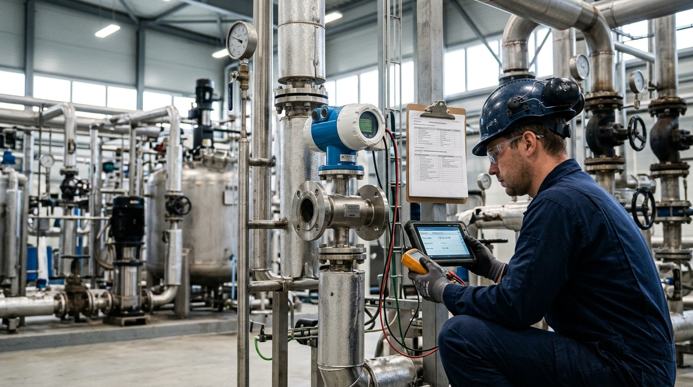
1. Applicable Scope and Key Parameter Verification
Electromagnetic flowmeters are applicable to liquids with conductivity generally not lower than 5 μS/cm; in engineering practice, it is more recommended that medium conductivity remain stable above 20 μS/cm. For a DN50 bore, the flow cross-sectional area is approximately 1.96×10⁻³ m². At a velocity of 0.5 m/s, the volumetric flow rate is approximately 3.5 m³/h; at 5 m/s, it is approximately 35 m³/h; and at 10 m/s, it is approximately 70 m³/h. In actual selection, DN50 electromagnetic flowmeters are often designed for a velocity range of 1–5 m/s, which ensures stable signal output while reducing lining wear and noise.
On site, the first step is to verify whether the nameplate parameters match the operating conditions, including nominal diameter DN50, pressure rating PN10/PN16/PN25, medium temperature, lining material, electrode material, protection rating, output signal, and grounding requirements. Common lining materials include PTFE, FEP, polyurethane, and ceramic; electrode materials may include 316L, Hastelloy C, titanium, tantalum, or platinum-iridium alloy. For acid, alkali, and salt solutions, chloride-containing media, or highly corrosive process liquids, corrosion selection cannot consider only the housing material; it must consider the lining, electrodes, seals, and flange faces in direct contact with the medium.
Note on Materials: If a device uses LGF-PA66 injection-molded one-piece structural components, they are usually used for terminal boxes, brackets, end caps, cable entry bases, or non-wetted structural parts. LGF-PA66 is long glass-fiber-reinforced polyamide 66. Compared with ordinary PA66, it offers better stiffness, dimensional stability, and creep resistance. However, PA66 itself is not a universal corrosion-resistant material. For truly wetted corrosive media, PTFE, FEP, ceramic, and similar linings should still serve as the primary corrosion barrier.
2. Pre-Installation Preparation
Process Confirmation
Check for bubbles, solids, temperature limits, and water hammer risks. DN50 is sensitive to partial filling.
Device Inspection
Verify no shipping damage. Check coil resistance (50–200 Ω) and insulation (>20 MΩ).
Tools & Materials
Prepare torque wrenches, multimeters, PTFE gaskets (1–3 mm thick), and grounding wires.
The third step is to prepare tools and installation materials. Common tools include torque wrenches, spirit levels, tape measures, multimeters, ground resistance testers, insulation tape, seal replacement tools, and tools for explosion-proof areas. Installation materials include PTFE gaskets, stainless steel bolts, grounding wires, grounding rings, waterproof connectors, conduits, and labels. For DN50 flanged connections, gasket thickness is typically controlled at 1–3 mm; excessive thickness may affect measuring tube geometry. The gasket inner diameter should be slightly larger than the pipe internal diameter, but it must not protrude into the measuring tube interior, otherwise local turbulence and reading deviation may occur.
3. Installation Procedure for DN50 Electromagnetic Flowmeters
The installation location should avoid strong magnetic fields, strong vibration, high-temperature radiation, and direct sun and rain exposure. If variable frequency drives, high-power motors, or induction heating equipment exist on site, signal cables and power cables should be routed separately and parallel runs should be avoided. DN50 sensors typically use flange mounting. Before installation, confirm pipe flange parallelism, alignment of bolt holes, and that sealing faces are clean and free of burrs. If pipe stress exists, release it through supports to prevent the flowmeter from bearing additional bending moments.
Straight-Pipe Run Requirements
- Upstream: Recommended at least 5D (250 mm for DN50). Extend to 10D (500 mm) if disturbances like pumps or elbows are present.
- Downstream: Recommended at least 2D (100 mm). Extend to 5D (250 mm) if upstream disturbances are significant.
The installation direction must strictly follow the arrow indication. When installed horizontally, the electrodes should be as close to the horizontal plane as possible, avoiding a vertical top-bottom orientation. The reason is that with vertical top-bottom installation, bubbles tend to attach to the upper electrode and sediments tend to deposit on the lower electrode, causing signal fluctuation or zero drift. For liquids that are easy to vent, horizontal installation facilitates venting; for wastewater or slurry containing solid particles, vertical upward installation is recommended so that particles are carried through by the flow, reducing deposition.
Grounding Installation
Grounding installation is the most easily overlooked yet most critical step on site. For metal pipes with good flange connections, a yellow-green grounding wire with a cross-sectional area no less than 4 mm² can be used to connect the sensor housing to the process grounding grid. If the pipe is plastic, fiberglass-reinforced plastic, or coated metal, grounding rings should be used so that the medium and measurement system form a reference ground. Grounding resistance is recommended to be controlled within 1 Ω and should not exceed 10 Ω during engineering acceptance. Poor grounding often manifests as empty-pipe alarm, zero drift, flow fluctuation, and sensitivity to ground interference.
4. Electrical Wiring, Grounding, and Commissioning Methods
Before electrical wiring, the power supply type must be confirmed. Common power supplies include AC 220 V ±15%, AC 110 V, and DC 24 V. On site, a power supply with fuse protection should be used, and terminals should clearly distinguish power, excitation, signal, communication, and grounding terminals. The 4–20 mA output load is generally required to be less than 600 Ω. If RS485 communication is used, a 120 Ω matching resistor should be added at the bus end, communication cables should be shielded twisted pair, and long parallel runs with power cables should be avoided.
Zero and Span Calibration
Zero calibration should be performed under full-pipe, no-flow conditions. Process-wise, the downstream or upstream valve of the flowmeter can be closed to make the medium stationary, confirm that the pipe is full and free of bubbles, and then perform zero calibration. It is recommended to perform zero calibration 2–3 consecutive times and observe repeatability. If the zero adjustment magnitude is large each time, this usually indicates poor grounding, electrode fouling, flow disturbance, or insufficient medium conductivity.
Span calibration can be completed by weighing method, portable ultrasonic flowmeter comparison method, or master-meter comparison method. Taking a DN50 device as an example, if the design velocity is 3 m/s, the theoretical flow rate is approximately 21 m³/h; comparison can be performed at approximately 20%, 50%, and 80% span points.
5. Routine Maintenance, Periodic Inspection, and Calibration
| Frequency | Key Actions |
|---|---|
| Weekly | Inspect display, instantaneous/cumulative flow, alarms, and transmitter surface temperature. |
| Monthly | Check grounding wire tightness, waterproof connector ingress, cable shields, and flange leaks. |
| Quarterly | Focus on electrode/lining condition. Clean deposits with soft cloth/neutral solution. Check for zero drift. |
| Annual | Calibration/comparison. Measure coil, insulation, and ground resistance trends. Inspect LGF-PA66 components for aging. |
For devices using LGF-PA66 injection-molded one-piece terminal boxes or protective structural components, maintenance should pay attention to material surface condition. PA66 has certain hygroscopicity, and long-term high-humidity environments may affect dimensions and insulation performance. If the terminal box surface shows powdering, cracks, obvious discoloration, whitening around bolt holes, or seal groove deformation, check whether the cause is chemical corrosion, UV aging, or over-tightened assembly. Fastener torque should be performed according to manufacturer specifications; plastic housings should generally not be over-tightened. Common small screw torque can be controlled within the 1–3 N·m range.
6. Common Troubleshooting and Field Cases
Fault: No Display / Transmitter Failure
Cause: Power voltage, fuses, wiring terminals, or moisture ingress.
Case: A DN50 device had its cable entry base loose in rainy season, causing terminal corrosion and flickering display.
Solution: Replace seal gasket, re-crimp terminals, install rain cover.
Fault: Flow Fluctuation / Unstable Reading
Cause: Bubbles, partial fill, poor grounding, pump pulsation.
Case: Fine chemical plant DN50 meter showed ±8% fluctuation due to short straight pipe (120mm) and gas accumulation.
Solution: Added 500mm upstream straight pipe, installed vent valve, reduced ground resistance to 0.8 Ω. Fluctuation dropped to ±1.5%.
Fault: Zero Drift
Cause: Electrode deposits, lining contamination, grounding ring corrosion.
Case: Wastewater plant DN50 reclaimed water line showed 0.6 m³/h zero reading when stopped.
Solution: Cleaned flocculent sludge from electrodes, replaced corroded grounding ring, recalibrated. Reading recovered to <0.05 m³/h.
Fault: Systematic High/Low Measurement
Cause: Reversed flow, span error, lining ID mismatch, cavitation.
Case: Batching system DN50 meter read 7% low after liner replacement.
Solution: Updated transmitter internal diameter parameter to match new PTFE liner. Deviation eliminated.
Fault: False Empty-Pipe Alarm
Cause: Low conductivity (<5 μS/cm), threshold settings, bubbles.
Case: Lab DN50 circuit alarmed frequently with high-purity water.
Solution: Confirmed conductivity was too low for EMF. Switched to different flowmeter principle or adjusted process (added salt). Do not simply lower threshold.
7. Maintenance Points for LGF-PA66 and Corrosion-Resistant Structures
The value of LGF-PA66 injection-molded one-piece structures in electromagnetic flowmeters is mainly reflected in protection consistency, assembly accuracy, and appearance stability in corrosive environments. Compared with multi-part assembled housings, injection-molded one-piece parts can reduce gaps and lower the probability of liquid and dust accumulation, making them more suitable for outdoor installation and humid workshops. However, it must be clarified that the core of electromagnetic flowmeter corrosion protection remains the wetted components: lining, electrodes, seals, and flange contact surfaces.
In field maintenance, LGF-PA66 components should be inspected with focus on three categories of condition:
- Chemical Compatibility: Check for swelling, stickiness, or powdering. Upgrade to PP, PVDF, or metal coatings if necessary.
- Thermal Aging: PA66 working temperature generally should not approach 100°C. Add insulation boards if near hot pipes.
- Mechanical Damage: Cracks in edges or screw holes compromise IP65/IP67 protection. Replace promptly rather than taping.
In corrosion pipeline retrofits, DN50 electromagnetic flowmeters are often paired with PTFE lining, Hastelloy electrodes, and stainless steel flange bolts. If a DN50 device uses an LGF-PA66 injection-molded one-piece terminal box, stainless steel screws and elastic sealing gaskets should be used to avoid electrochemical corrosion caused by long-term contact of dissimilar materials. Cable entry bases should also match the housing material to prevent seal failure due to differences in coefficient of thermal expansion.
8. Outlook: Standardized Installation and Digital Operations
Many field problems with electromagnetic flowmeters are not caused by device failure itself, but by inadequate installation, grounding, process fluctuation, and maintenance cycle management. As the process industry’s requirements for metering accuracy, safety interlocks, and energy efficiency management increase, application scenarios for small-bore electromagnetic flowmeters such as DN50 will become more segmented. Future engineering practice will place greater emphasis on standardized installation templates, parameterized commissioning records, and predictive maintenance.
Digital tools are also changing maintenance methods. Transmitters can form trend data for coil resistance, insulation resistance, zero drift, empty-pipe alarm count, cumulative flow deviation, and grounding status. For devices using LGF-PA66 injection-molded one-piece structures, maintenance personnel can combine inspection photos, torque records, and material aging images to establish life assessment files. Compared with troubleshooting after failure, trend-based maintenance is more effective in reducing unplanned shutdowns. Industry application experience shows that long-term stable operation of electromagnetic flowmeters depends not only on sensor materials and corrosion design, but also on field installation quality, commissioning methods, and maintenance discipline. Only by incorporating velocity, full-pipe condition, grounding, electrode fouling, and material compatibility in DN50 small-bore operating conditions into a unified management system can accurate, reliable, and maintainable online metering be achieved.

