How to Choose the Right Electromagnetic Flowmeter? Accuracy and Stability Are Key
In industrial process metering, electromagnetic flowmeters have long served as a core technology for measuring the flow of conductive liquids. Compared with vortex-shedding, turbine, ultrasonic, and Coriolis mass flowmeters, electromagnetic flowmeters are highly adaptable to particulate-laden, fiber-laden, corrosive, and conductivity-stable liquids. However, different technology paths differ markedly in excitation method, liner and electrode materials, corrosion-protection structure, bore-size design, and installation conditions. Focusing on keywords such as LGF-PA66, injection-molded integration, corrosion protection, and DN50, one can see that small-bore conductive-liquid metering is not simply a matter of selecting bore size and material; it requires simultaneously balancing accuracy, stability, medium compatibility, and maintenance cost.
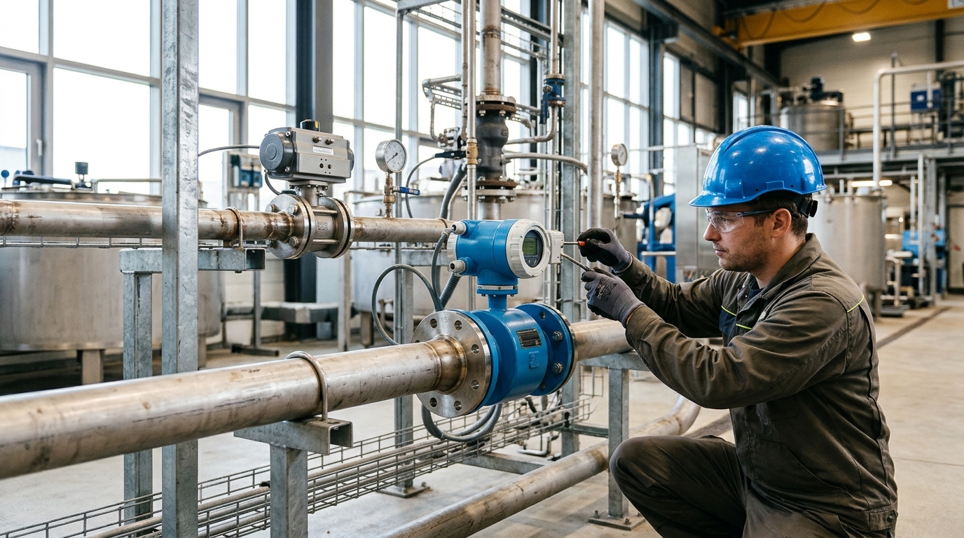
1. Measurement Principle and Technology Path: Which Conductive Liquids Are Suitable?
Electromagnetic flowmeters operate based on Faraday's law of electromagnetic induction. When a conductive liquid flows through a magnetic field, an induced electromotive force is generated on electrodes perpendicular to both the magnetic field and the flow direction. Its magnitude is approximately proportional to the average velocity and can be expressed by the simplified relationship $E = kBDv$. Here, $B$ is magnetic flux density, $D$ is the inner diameter of the measuring tube, $v$ is the average liquid velocity, and $k$ is a coefficient related to magnetic-field distribution and electrode structure. This principle means electromagnetic flowmeters have basic requirements for medium conductivity; the common industry threshold is conductivity no lower than 5 μS/cm. Conventional electromagnetic flowmeters are not suitable for deionized water, high-purity chemicals, oils, gases, or steam.
From a technology-path perspective, the core differences among electromagnetic flowmeters are concentrated in excitation method, sensor structure, electrode and liner materials, signal-processing algorithms, and installation form.
Vs. Vortex & Turbine
Electromagnetic flowmeters are less affected by changes in density, viscosity, temperature, and pressure, offering a wider turndown ratio (20:1 to 100:1). They also lack moving parts, making them more tolerant of particle-laden slurries compared to turbines.
Vs. Ultrasonic & Coriolis
Compared to ultrasonics, they require less straight-pipe length. Compared to Coriolis meters, they are lower in cost and pressure loss but cannot directly measure mass flow.
The DN50 bore is a small-to-medium bore suitable for fine chemicals, circulating water, acid-alkali liquid circuits, laboratory dosing systems, and municipal branch-metering. However, small bores are more sensitive to minimum velocity and full-pipe conditions.
2. Comparison of Excitation Methods
The excitation method determines how the magnetic field is generated and directly affects zero stability, noise immunity, and slurry-noise performance.
- Power-Frequency AC: Synchronized with 50 Hz grid. Strong suppression of power-frequency interference but higher power consumption and potential flow noise in slurries.
- Low-Frequency Rectangular-Wave: Reduces frequency to ~16-50 Hz. Lowers slurry noise and power consumption. Common choice for clean water and general chemicals.
- Dual-Frequency: A compromise ensuring zero stability (low freq) and suppressing slurry/bubbles (high freq). Can improve accuracy from ±1.0% to ±0.5% in pulp/sludge scenarios.
- Permanent-Magnet: No coil required. Simpler structure, low power. Suitable for battery-powered small bores, but accuracy is typically lower (±1.0% to ±1.5%) and sensitive to temperature/magnet aging.
For DN50 small-bore circuits with fluctuating flow rates (2–15 m³/h), low-frequency rectangular-wave or dual-frequency excitation is usually more stable than permanent-magnet schemes.
3. Liners, Electrodes, and Corrosion-Protection Structures
Corrosion protection is a systems-engineering matter jointly determined by the liner, electrodes, housing, insulating flanges, grounding system, and medium compatibility.
| Component | Common Materials | Application Focus |
|---|---|---|
| Liners | Rubber, Polyurethane, PTFE, PFA, Ceramic | Wear resistance vs. Chemical resistance |
| Electrodes | 316L SS, Hastelloy, Titanium, Tantalum, Pt-Ir | Corrosion resistance based on pH/Cl- |
| External Structure | LGF-PA66 Injection-Molded Integration | Sealing against ingress, rigidity, insulation |
LGF-PA66 (Long Glass-Fiber reinforced Polyamide 66) offers better rigidity, dimensional stability, and creep resistance compared to ordinary nylon. Injection-molded integration reduces assembly gaps, lowering the probability of corrosive media penetration along threads and flange faces. For DN50 service involving dilute HCl, brine, or weak alkalis, combining PTFE liners, Tantalum/Hastelloy electrodes, and LGF-PA66 external structures achieves good stability at 1.0–1.6 MPa and -20℃ to 120℃. Note: Compatibility verification is still required for strong oxidizing acids and UV exposure.
4. Bore Size and Installation Conditions: DN50 Flow Boundaries
DN50 has an inner diameter of ~50 mm and cross-sectional area of ~1.96×10⁻³ m². Velocity calculations indicate:
(Min Recommended)
(Standard)
(High Flow)
If flow remains long-term below 2 m³/h, DN50 may enter a low-velocity region causing zero drift. Consider DN40/DN32. If flow exceeds 20 m³/h, evaluate pressure loss and liner erosion.
Installation Best Practices
Industry experience requires upstream straight-pipe length ≥ 5D and downstream ≥ 2D. Shortening these distances increases error significantly.
Case Study: In a wastewater return-sludge DN50 application, reducing upstream straight pipe from 5D to 2D increased reading fluctuation from ±0.8% to ±2.5% and caused empty-pipe false alarms, demonstrating that pipeline disturbances are as critical as sensor accuracy.
5. Selection for Different Medium Scenarios
6. Signal Processing, Grounding, and Empty-Pipe Detection
Output signals are at microvolt levels. Modern digital converters use synchronous sampling and correlation detection. Diagnostics include empty-pipe detection, coil resistance testing, and zero-stability checks.
- Grounding: Recommended resistance < 10 Ω (ideally 1–5 Ω). Poor grounding causes zero drift due to common-mode voltage.
- Insulation: Excitation coil insulation resistance > 100 MΩ.
- Empty-Pipe: Detects non-full pipes via impedance comparison. False alarms can occur due to low conductivity, bubbles, or fouling.
Process piping design matters. Adding vent valves and increasing pipe slope resolved frequent empty-pipe alarms in a chemical DN50 circuit, proving that installation geometry complements sensor technology.
7. Selection Recommendations and Future Outlook
Selection should start from medium conditions and maintenance costs, not just accuracy classes. Follow this checklist:
- Confirm conductivity > 5 μS/cm and absence of large bubbles/non-conductive particles.
- Determine bore size and velocity (DN50 ideal for 2–15 m³/h).
- Select excitation method based on medium cleanliness and noise sensitivity.
- Choose liner and electrode materials via a compatibility matrix.
- Ensure proper installation: 5D/2D straight pipes, grounding, venting, and full-pipe conditions.
Future evolution will emphasize material databases, online diagnostics, and digital twins. While LGF-PA66 injection-molded integration improves sealing and modularity, true reliability comes from finding the most stable technology combination under specific medium and installation conditions, rather than pursuing highest parameters alone.

