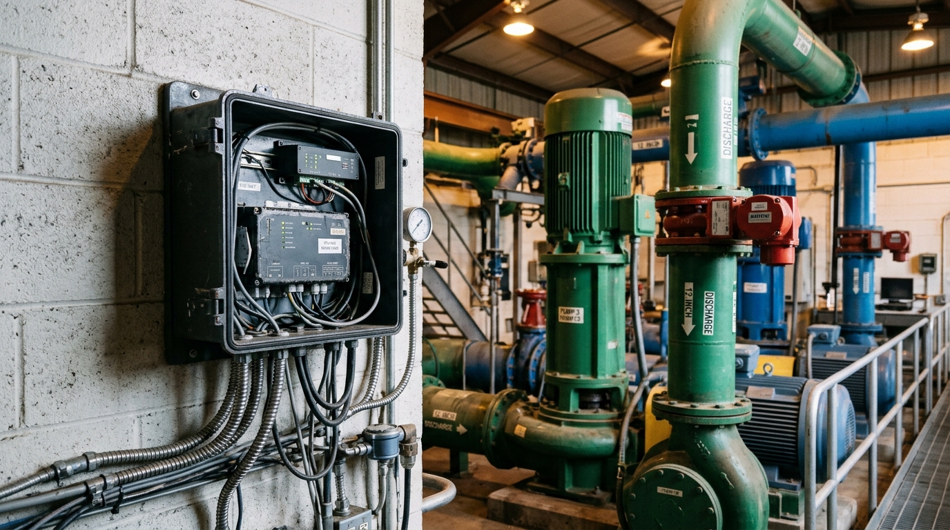
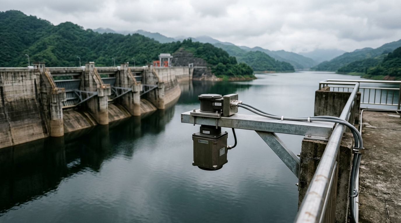
IoT RTU Deployment in Irrigation Districts: A Field Engineering Guide to Power, Communications, and Long-Term O&M
Navigating the structural difficulties of agricultural telemetry requires a shift from urban-centric designs to rugged, low-power, and maintenance-light engineering principles.
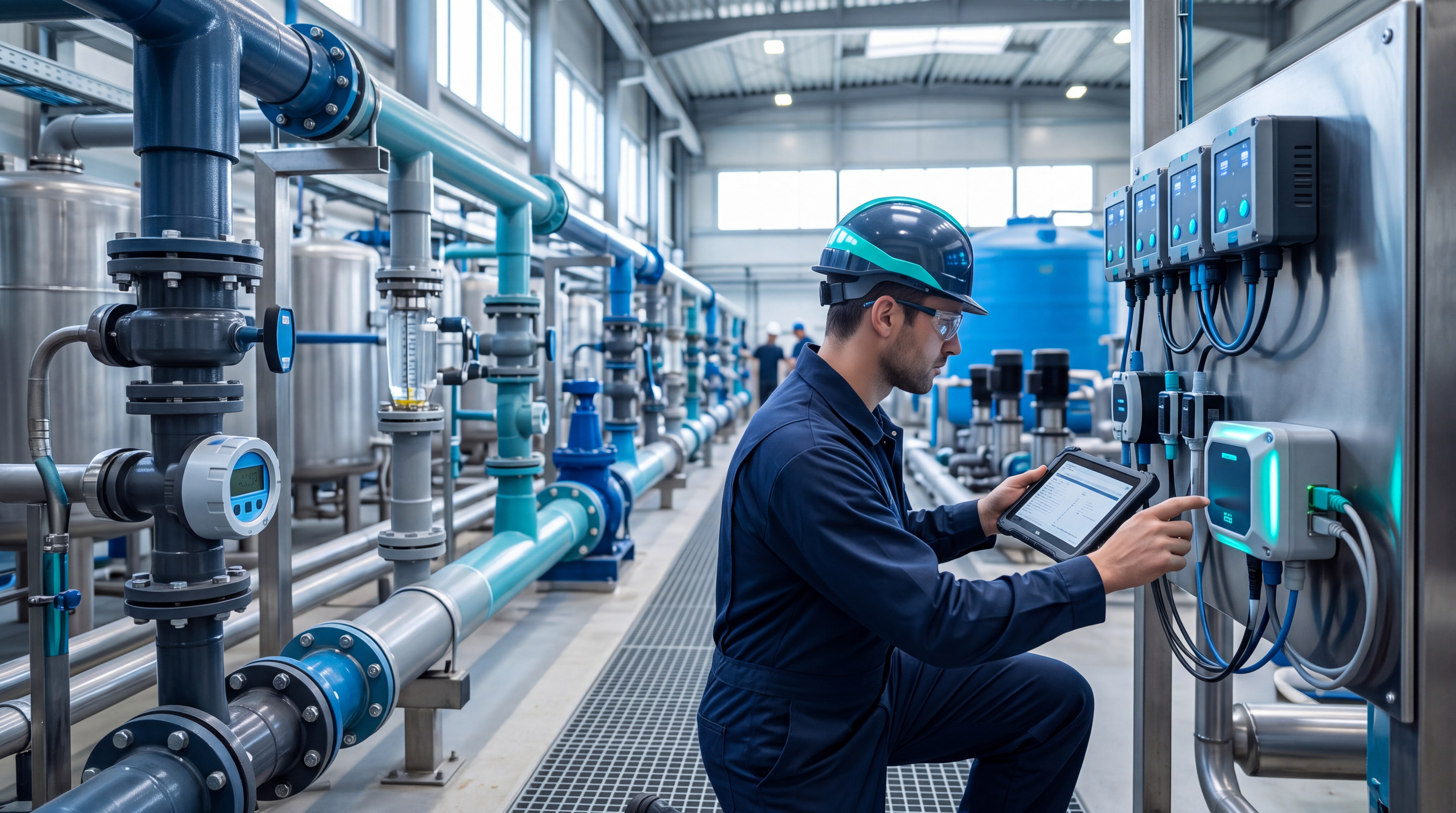
01 Background: Why Irrigation Districts Are the Toughest Telemetry Environment
Irrigation districts account for the majority of agricultural water withdrawal worldwide, yet most main-canal metering points still lack reliable data acquisition. Compared with urban water utilities, irrigation telemetry faces three structural difficulties:
- Extreme point dispersion: A medium-sized district's main canal routinely exceeds 50 km with monitoring points several kilometres apart.
- Absent infrastructure: Most headworks and division gates sit in open country with no grid power and weak cellular coverage.
- Large maintenance radii: A single inspection round trip can take hours, so equipment failures go unnoticed for days.
These constraints make "low power, self-powered, maintenance-light" the primary design principle for any district telemetry system.
02 RTU Selection: Four Critical Specifications
The remote terminal unit (RTU) is the hub of the entire monitoring chain. Four specifications deserve priority attention:
Power Consumption
Sleep current below 50 µA, with both scheduled wake-up acquisition (e.g., every 30 minutes) and event-triggered reporting modes — a prerequisite for any solar-autonomous system.
Interface Capacity
At minimum 2× RS-485 (Modbus RTU) for radar level sensors, Doppler velocity meters, and gate-position encoders; 2× 4–20 mA analogue inputs; and 2× pulse inputs for tipping-bucket rain gauges.
Protocol Compliance
Native support of national hydrological telemetry standards (in China, SL 651-2014) for direct provincial-platform integration, plus MQTT/HTTP for the district's own SCADA layer.
Environmental Rating
–20 °C to +70 °C operating range, IP65 minimum enclosure, hardware watchdog, and store-and-forward buffering to guarantee data integrity in unattended operation (aligned with IEC 60068).
03 Power Budget and Communications Architecture
Power Sizing Strategy
Power sizing works backwards from the required autonomy in consecutive overcast days. For a northern-climate district assuming 7 sunless days and 24 acquisition-transmission cycles per day:
- The RTU averages ~0.9 Wh/day.
- Adding sensors and the radio, system draw is ~3.5 Wh/day.
- Proven Configuration: 20 W monocrystalline panel + 12 V / 20 Ah LiFePO4 battery (~200 Wh usable) with 30% design margin.
⚠️ Mount the battery underground or in a ventilated cabinet — sustained high temperatures measurably shorten cycle life.
Communications Architecture
Communications should follow a three-tier "4G primary, LoRa aggregation, satellite fallback" architecture:
Tier 1: Primary
Sites with good coverage report directly over LTE Cat.1.
Tier 2: Aggregation
Weak-signal sites backhaul via LoRa (3–5 km line-of-sight) to a headworks node.
Tier 3: Fallback
Canal reaches with zero cellular coverage use short-message satellite links as an emergency channel.
Field deployments show this hybrid design cuts cellular data costs by roughly 40% versus an all-4G design while lifting site availability above 99%.
04 Installation and Commissioning Practice
Lightning Protection
In open terrain, lightning is the leading cause of RTU failure. Bond the panel frame, RTU enclosure, and antenna-cable shield to a common earth electrode of ≤10 Ω, and fit SPD surge protectors on both power and signal entries.
Siting & Cabling
Mount the RTU cabinet beside the canal inspection road within 10 m of the measurement cross-section. Route all cabling in galvanised conduit with waterproof sealing at both ends.
Commissioning Sequence
- Verify raw sensor readings locally against a staff gauge (tolerance ±2 cm).
- Confirm platform data reception, threshold alarms (immediate report on level excursion), and remote parameter configuration.
- Run a 72-hour soak test — accept only at ≥99% data completeness.
Conclusion
The success or failure of irrigation district telemetry rests not on any single device but on system-level low-power design, power redundancy, and lightning-protection detail. Sites deployed to the above standard have sustained annual availability above 99.5% with fewer than two maintenance visits per station per year across multiple district modernisation projects.
Districts beginning their digital upgrade should prioritise RTU coverage at headworks intakes and division gates — the two node classes that yield the greatest operational value for water-allocation scheduling at minimum investment.