IoT RTU Deployment in Pump Stations: An Engineering Guide from Unattended Retrofit to Predictive Maintenance
Engineering • Industrial IoT • Smart Water Infrastructure
Background: From Unattended Operation to Intelligent O&M
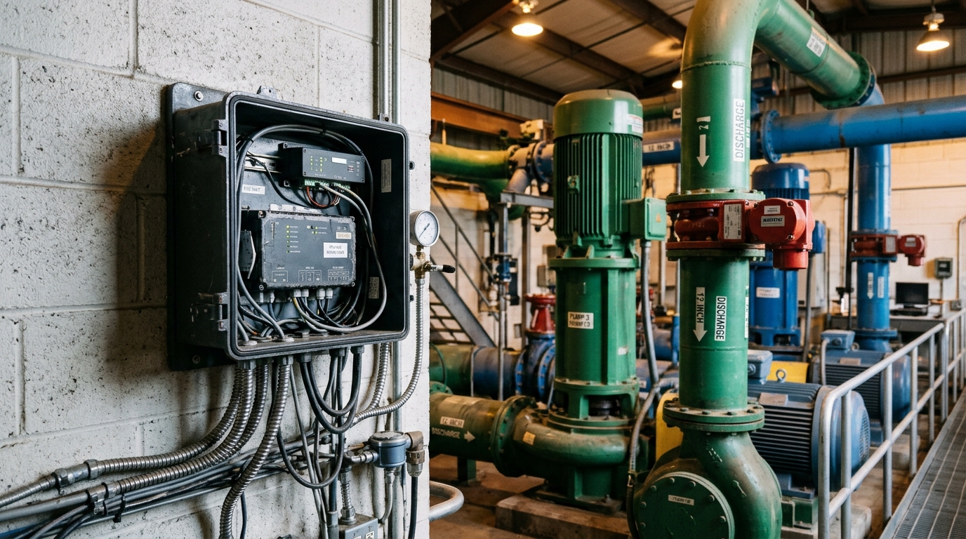
Pump stations are the power hubs of urban water lifelines. Hundreds of thousands of booster stations, drainage pump stations and irrigation pumping plants are in operation worldwide, and many still follow an "unattended + periodic inspection" model: equipment condition depends on weekly or monthly site visits, while progressive faults such as bearing wear, mechanical seal leakage and impeller cavitation develop silently — often surfacing only as a tripped unit or a flooded station, with high repair costs and service interruption risk.
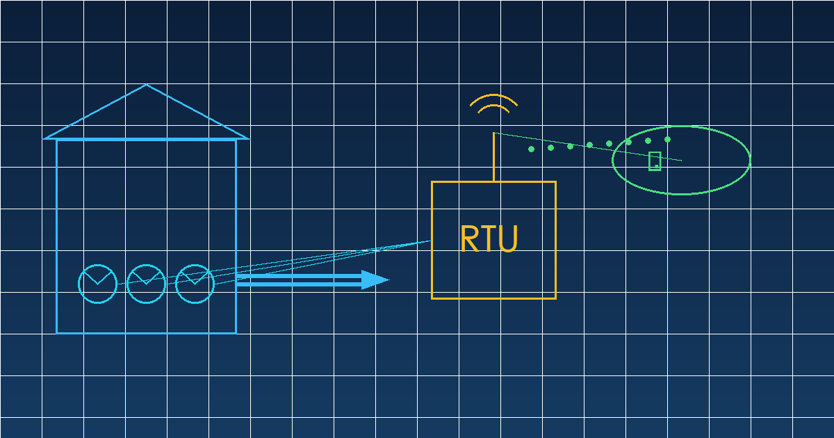
The proven engineering path is to deploy an IoT RTU (Remote Terminal Unit) as the station's data gateway, digitize the electrical, mechanical, process and environmental parameters, and build a predictive maintenance loop of real-time sensing, trend analysis and early warning.
Technical Analysis: Four Acquisition Dimensions for Condition Monitoring
1 Electrical Parameters
Split-core current transformers capture three-phase voltage, current, active power and power factor. Field experience shows that a sustained three-phase current imbalance above 10% usually indicates phase loss or winding anomalies, while rising current with falling flow points to impeller wear or pipeline fouling. Cross-checking electrical signatures against process variables is the lowest-cost early fault indicator.
2 Vibration and Temperature
Vibration sensors on bearing housings and motor ends measure velocity RMS. Following the severity zones of ISO 10816 / ISO 20816-3, sustained bearing vibration above 7.1 mm/s enters the alarm zone. Combined with PT100 winding and bearing temperatures, this covers roughly 80% of common rotating-machinery failure modes.
3 Process Parameters
Suction/discharge pressure, flow and sump level are the basic operating variables. Plotting flow against head yields the real-time operating point; comparing it with the manufacturer's characteristic curve quantifies efficiency drift. A five-point efficiency drop typically precedes any visible mechanical symptom — the most valuable leading indicator for predictive maintenance.
4 Environmental Parameters
Sump flood level, temperature/humidity (condensation and cooling), smoke detection and door status form the baseline station-safety package: sensor costs are minimal, but they prevent major secondary incidents.
Solution Recommendations: Four Design Points for RTU Deployment
- Communication architecture: 4G/NB-IoT as the primary link; the RTU polls VFDs, smart meters and sensors via RS485/Modbus RTU. Critical stations should add a wired Ethernet backup, with MQTT support for direct cloud integration.
- Power design: Mains plus lithium battery backup with at least 72 hours of autonomy; RTU sleep current should be in the 50 µA class so low-frequency heartbeat reporting survives outages.
- Tiered sampling strategy: Electrical and process data sampled at second-level resolution and uploaded per minute; vibration acquired in timed bursts (e.g., 10 s at ≥1 kHz), with FFT performed at the edge so only spectral features are transmitted — keeping monthly traffic per station under 100 MB.
- Predictive maintenance loop: Establish parameter baselines during the first two weeks, then alarm on both trend slope and absolute thresholds; estimate remaining useful life of bearings and seals from vibration trends, converting unplanned breakdowns into scheduled maintenance.
Conclusion
Smart pump stations are not about stacking sensors but about choosing the right acquisition dimensions and sustaining a closed data loop. The RTU-centered four-dimension scheme keeps per-station hardware cost and installation time (typically under one day) low, while the gains in early fault detection and O&M efficiency usually repay the investment within a year. For utilities advancing Smart Water and Urban Lifeline programs, pump station condition monitoring is the highest-priority quick win.