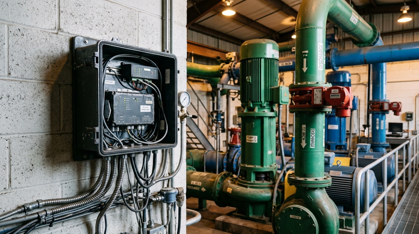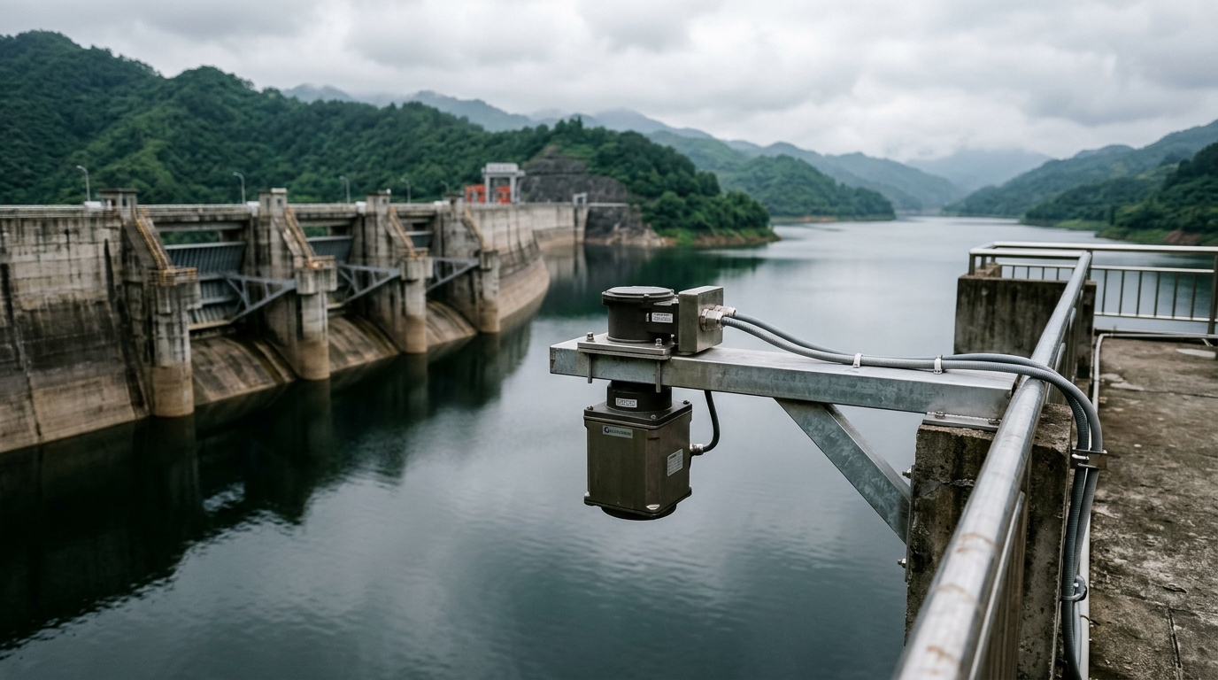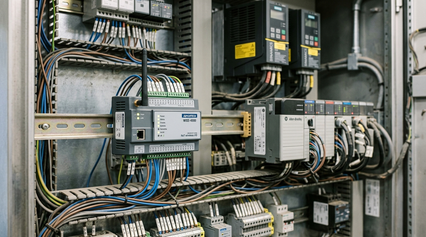
Pump stations are the workhorses of any Smart Water network — and also one of its most hostile electromagnetic environments. Variable frequency drives (VFDs), soft starters and large induction motors are concentrated in a small space, generating switching transients and harmonic noise that routinely corrupt telemetry. Field engineers report the same triad of symptoms after installing an IoT RTU: drifting 4–20 mA analog readings, dropped RS485 frames, and sporadic watchdog resets. In most cases the RTU itself is fine; what is missing is an EMC-aware system design.
Where the interference comes from: three coupling paths
A VFD synthesizes its output by PWM switching with dv/dt values of 5–10 kV/μs. The resulting conducted emissions concentrate in the 2–150 kHz band, and they reach the RTU through three paths:
- Conducted coupling: noise travels along shared power and signal wiring into the RTU's supply and I/O ports, showing up as unexplained jumps in analog channels.
- Radiated coupling: DC busbars and motor cables act as antennas, inducing common-mode voltages in nearby low-level circuits — millivolt thermocouple inputs and pulse counters are hit first.
- Ground loops: different points of the station ground grid can differ by several volts during motor starting. If cable shields are grounded at both ends, circulating currents develop a voltage drop that adds directly to the measured signal.
A four-layer mitigation scheme
1. Power. Feed the RTU from a dedicated circuit, physically separated from VFD power inside the panel. Apply two-stage protection: a surge protective device (SPD, In ≥ 20 kA, 8/20 μs waveform per IEC 61643-11) for lightning and switching surges, followed by an isolated DC-DC converter (≥ 1.5 kV isolation) to break the conducted path. In our field measurements this reduced analog noise from ±2% FS to below ±0.2% FS.
2. Signals. Use two-wire 4–20 mA transmitters with isolated outputs, and twisted-pair shielded cable with the shield grounded at the RTU end only. Specify RTUs with galvanically isolated analog inputs (≥ 500 V channel-to-channel) and opto-isolated pulse inputs with digital filtering — a 10–50 ms time constant is a good compromise between noise rejection and response time. Equipment should carry IEC 61000-4-4 (burst) and IEC 61000-4-5 (surge) test evidence at level 4.
3. Communications. RS485 interfaces must be isolated and TVS-protected. Route the bus away from power cables; cross them at 90° and keep at least 30 cm of parallel separation. For backhaul beyond 1 km to the SCADA center, a dual-link architecture — LTE/4G primary with fiber backup — is the most robust choice, since fiber is inherently immune to EMI.
4. Installation. Keep the RTU cabinet at least 1.5 m horizontally from VFD cabinets, or insert a galvanized steel barrier where space is tight. Bond the RTU cabinet ground with ≥ 16 mm² copper to the station equipotential bar; station ground resistance should be ≤ 4 Ω.
Conclusion
The real challenge of pump-station telemetry is not acquisition but stability. Treat EMC as a design input equal in weight to instrument selection: power isolation breaks conducted paths, single-point grounding eliminates loops, dual-link backhaul guarantees data delivery, and physical separation reduces radiated coupling. Projects built on this four-layer scheme typically see field fault tickets drop by more than 80% and data completeness held above 99.5% — a dependable foundation for unmanned pump stations and Urban Lifeline monitoring.