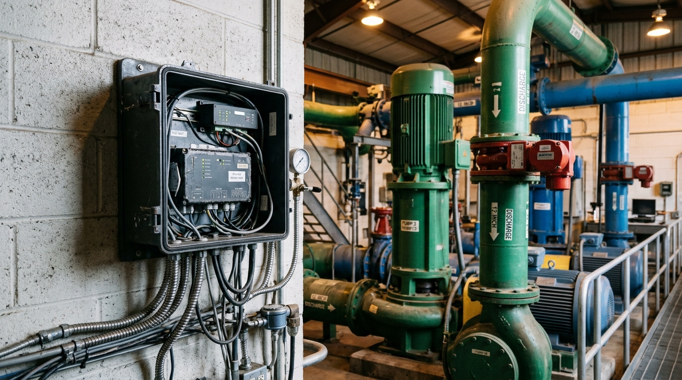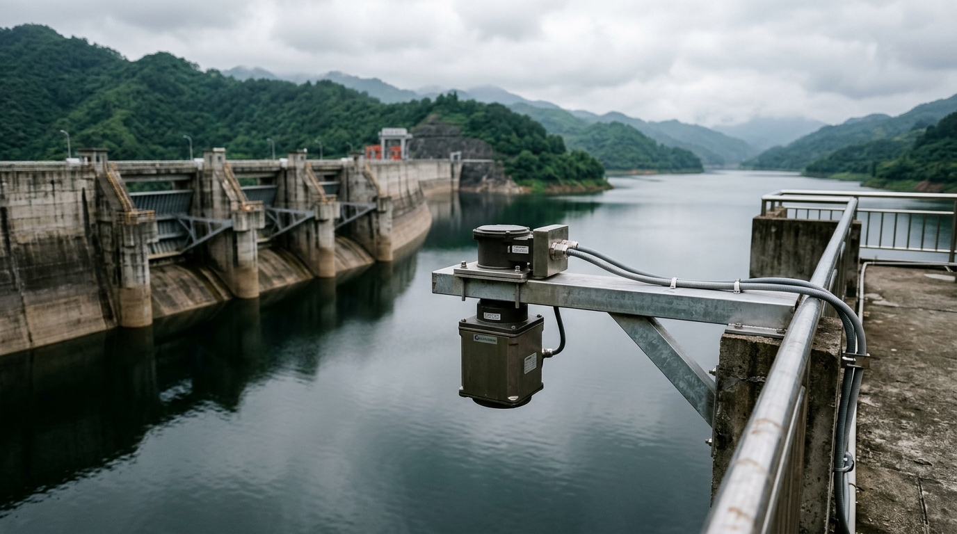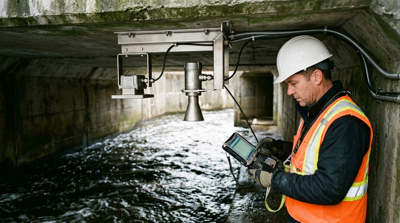
Background: Why Non-Contact Measurement Dominates Drainage Monitoring
Urban stormwater box culverts operate in one of the harshest metering environments: high humidity, H₂S-driven corrosion, alternating free-surface and surcharged flow, and destructive flood peaks. Invasive Doppler meters require wet drilling, remain permanently submerged and are vulnerable to fouling and scour damage. Over the past three years, non-contact radar surface velocity sensing has matured into the preferred technology for sewer flow monitoring and smart water networks.
Technical Analysis: Three Non-Contact Routes Compared
- 80 GHz radar (λ ≈ 3.8 mm): narrow beam widths of 4°–8° allow precise aiming at the maximum-velocity zone in confined culverts. Proven detection over 0.05–15 m/s surface velocity, with superior immunity to rain clutter and surface turbulence versus 24/26 GHz designs. Integrated radar level modules output water depth and surface velocity simultaneously.
- 26 GHz radar: wider beam (10°–12°) produces side-wall clutter in culverts wider than 3 m, but remains cost-effective for open channels.
- Clamp-on ultrasonic: advantageous for full-bore pressurised flow with zero wetted parts, yet suffers from signal attenuation in large-diameter, partially filled or aged-lining pipes, and provides no air-gap information.
Critically, surface velocity is not mean cross-sectional velocity. Radar senses the top 10–20 mm of the flow; a velocity correction factor k (typically 0.85–0.92, dependent on depth and wall roughness) must be applied. Advanced instruments embed multi-point calibration models that adjust k dynamically with stage, holding discharge error within ±5% under free-surface conditions.
Engineering Recommendations for Culvert Deployment
- Site selection: install on a hydraulically smooth straight reach, clear of weirs, confluences and pump suction disturbances; provide at least 5 water-depths of upstream straight run. Aim the beam centreline at the channel centre within the specified air-gap range (commonly 0.2–10 m).
- Calibration: perform 3–5 comparative measurements with a portable Doppler or current meter at different stages during commissioning, and back-calculate k into the device. This step is non-negotiable for accuracy acceptance.
- Protection & power: use IP68 stainless-steel brackets rated for flood impact; size batteries with low-temperature derating, paired with NB-IoT/4G low-power reporting (e.g. 15-minute intervals) for 3–5 year autonomous operation.
- Data quality control: flag surcharged states (zero air gap) and radar lock-loss separately so invalid returns never enter the flow database.
Conclusion
80 GHz radar surface velocity sensing — non-invasive, no pipe cutting, and combined stage-and-velocity output — is displacing invasive Doppler meters as the backbone of urban drainage monitoring (a key element of urban lifeline infrastructure and low-cost sensing strategies). Project success hinges less on the sensor than on three disciplines: installation geometry, correction-factor calibration and data quality governance. System integrators should specify instruments with built-in auto-correction and field calibration workflows, and enforce comparative gauging during commissioning.