1. Background: Why Non-Contact Flow Measurement Is Winning New Monitoring Points
Gravity sewers, irrigation tail canals and outfall conduits share the same hostile metering environment: alternating full/partial pipe flow, H₂S corrosion, grease and foam build-up, and flood-season velocity surges. Intrusive devices — insertion magmeters, wet Doppler probes — require hot tapping or pipe cutting, and their wetted parts drift as scale accumulates. Non-contact measurement physically separates the sensing element from the water, which is why it has become the default choice for new Urban Drainage Monitoring points. This article compares the two dominant non-contact routes — radar surface velocimetry and clamp-on ultrasonic transit-time metering — and outlines field-proven accuracy verification methods.
2. Technical Analysis: Radar Surface Velocimetry vs Clamp-On Ultrasonic
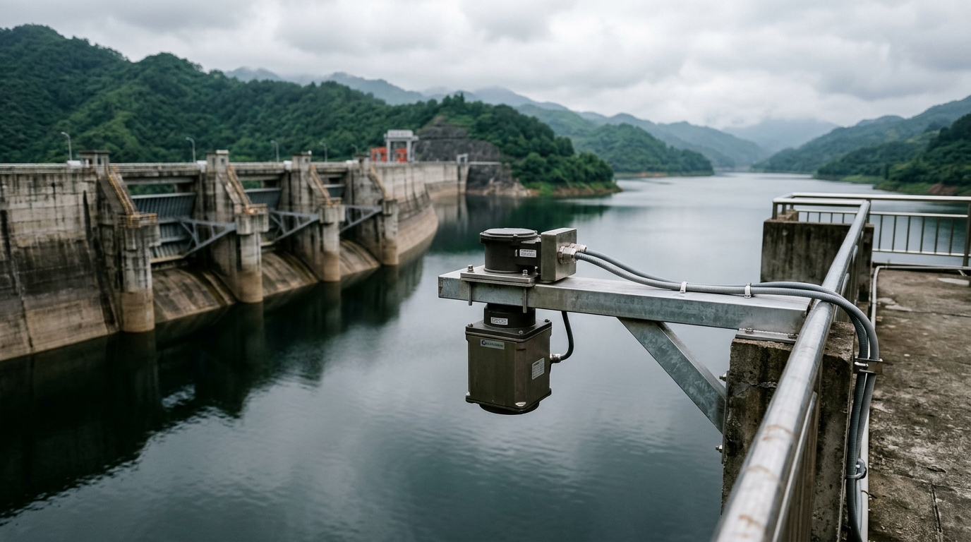
Non-contact radar velocimetry measures surface velocity via the Doppler shift of a focused microwave beam and, combined with a radar level meter, forms a velocity-area flow system. Modern 80 GHz planar radar achieves beam angles around 4°, with typical accuracy of ±1% of reading or ±0.02 m/s (whichever is greater) over 0.2–15 m/s. Its decisive advantages: no wetted parts, installation above manholes or channel covers, and IP68 housings tolerant of temporary submersion. The trade-off is that only surface velocity is measured, so a surface-to-mean velocity coefficient of roughly 0.80–0.90 must be applied — and that coefficient varies with water depth and channel roughness.
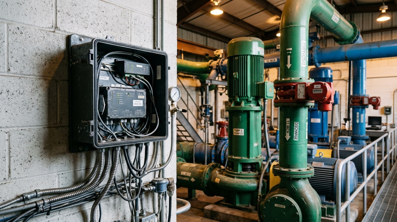
Clamp-on ultrasonic (transit-time) transducers mount on the pipe exterior and serve pressurised full-pipe flow from DN50 to DN6000 with zero pressure loss and no process interruption. Accuracy degrades, however, with wall condition: cast-iron wall-thickness variation, degraded lining and aged coupling gel typically add 2–5% uncertainty, and partial-pipe sections simply cannot be measured.
Selection rule of thumb: gravity flow, partial pipes and manhole installations favour radar surface velocimetry; pressurised full pipes (pump discharge, rising mains) favour clamp-on ultrasonic. For wide shallow channels where no reliable velocity coefficient can be established, pair a standard weir or Parshall flume with a radar level meter — shifting the uncertainty budget from hydraulics coefficients to surveyed geometry.
3. Engineering Practice: Verifying Accuracy in the Field
The largest risk in non-contact metering is not hardware failure but silent systematic bias. Three verification paths, in ascending cost:
- On-site coefficient calibration: during dry weather, measure the true mean velocity at the same cross-section with a portable ADCP or float-area method, then derive the actual surface-to-mean coefficient and write it into the RTU instead of trusting factory defaults;
- Volumetric cross-check: where a downstream wet well or balancing tank exists, compute period volume from level change × tank capacity and compare against the flow totaliser; deviation should stay within ±5%;
- Edge-side data QA: run threshold and gradient rules on the IoT RTU (flag velocity steps >2 m/s, alarm on stage-discharge deviation from the historical curve), with daily heartbeat and store-and-forward recovery to keep platform data availability above 98%.
When deploying these sensors as a Low-cost Sensing layer of a Smart Water platform, a dual-mode sampling strategy — 15-minute routine logging plus rain-triggered 1-minute intervals — balances battery life against event resolution.
4. Conclusion
Neither radar nor clamp-on ultrasonic is universally superior; boundary conditions — full vs partial pipe, pipe material, site accessibility — decide the route. Long-term data credibility depends on turning calibration, volumetric cross-checks and edge QA into scheduled O&M routines. Integrators should deliver a site-specific calibration report together with each non-contact metering point: that is the difference between installing a sensor and delivering auditable flow data.