Why Radar Dominates Open-Channel Level Measurement
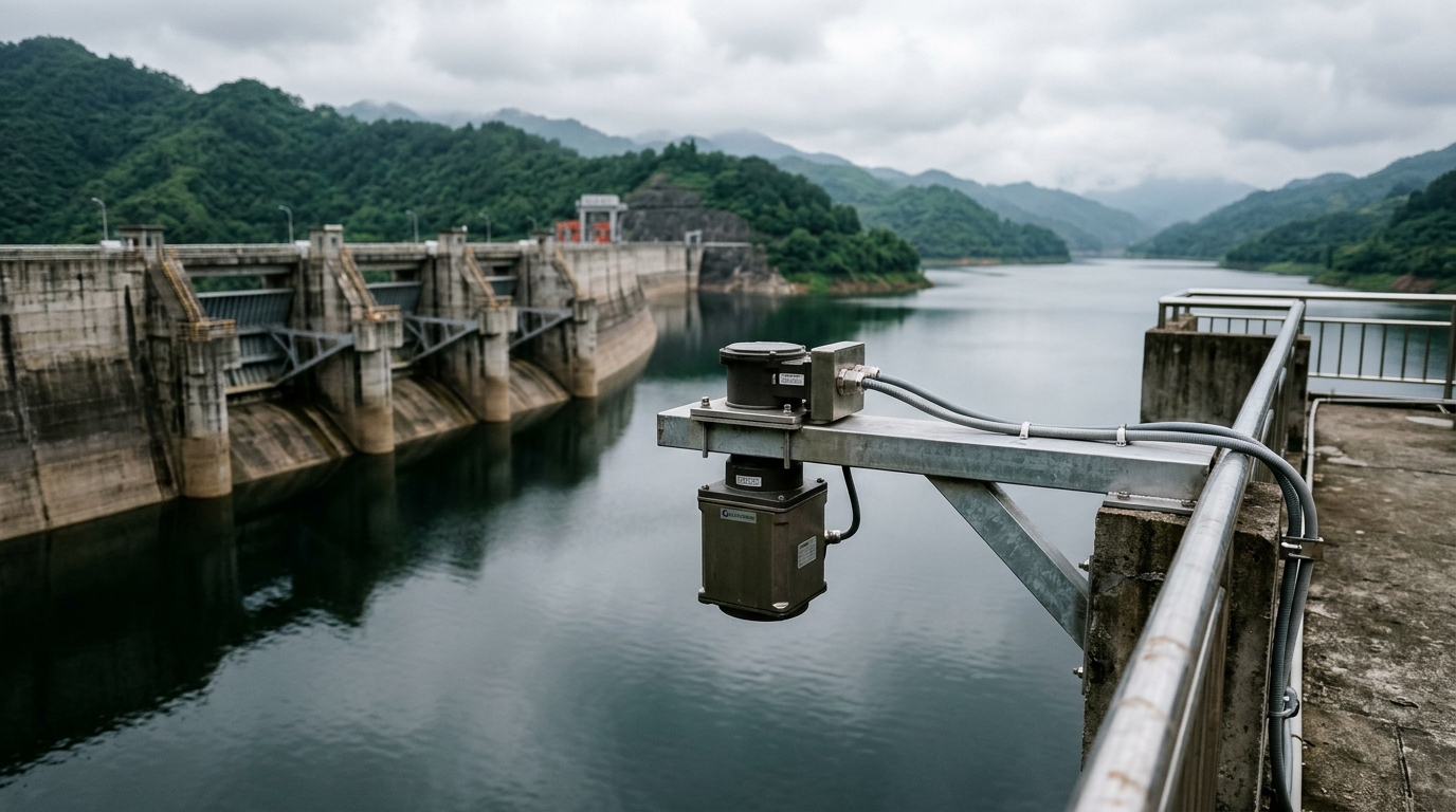
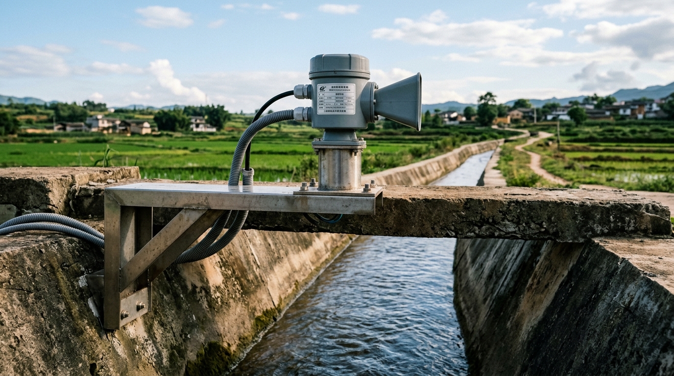
Open channels expose the water surface to debris, vegetation and highly variable flow. Submersible pressure transducers suffer from silt clogging and biofouling, while float-based systems jam on debris. Non-contact radar level meters, mounted on a bracket or gantry above the channel, eliminate wetted parts entirely and have become the default choice for canal, river and stormwater monitoring under smart water programmes.
Technical Analysis: 80 GHz FMCW in the Field
Modern open-channel radar gauges use 80 GHz FMCW technology with a narrow beam angle of 3°–8°. At a 10 m mounting height the footprint is only 0.5–1.4 m in diameter, allowing the beam to clear channel walls, railings and bank vegetation. Typical specifications: measuring range 0.05–30 m, resolution 1 mm, accuracy ±1–3 mm on calm water. These devices are usually qualified to IEC 60068 environmental test sequences (vibration, temperature cycling) and rated IP67/IP68 for the antenna housing.
The three dominant interference mechanisms in open channels:
- Surface turbulence: near weirs and sluice gates the returning echo spectrum broadens. Mitigate by selecting a tranquil straight reach and enabling the instrument's multi-echo averaging (16–64 samples) and false-echo suppression learning curve.
- Beam obstruction: reeds, trash racks and foam can intrude into the beam cone. Verify clearance visually or with a laser pointer before fixing the bracket; raise the mounting by 0.5–1 m if needed.
- Bracket vibration: wind-induced oscillation of cantilever mounts smears the echo. Keep cantilever length ≤1.5 m, add diagonal bracing, and check the natural frequency against expected wind loading.
Engineering Recommendations
Siting: choose a straight reach with at least 5 channel-widths upstream and 2 downstream of the sensor, clear of bends and hydraulic jumps. Maintain a dead-zone clearance of ≥0.5 m above the highest expected water level, and select a range with ~20 % margin over the channel depth.
Verticality: the beam axis must be perpendicular to the still-water surface. A tilt of θ introduces a systematic error of h(1/cosθ − 1) — a 5° tilt at 5 m yields roughly 19 mm bias. Level the mount with a dual-axis bubble and confirm via echo strength (main echo should be unique and stronger than −70 dBm).
Three-point calibration: compare against a staff gauge at low, mid and high stages. If deviation exceeds ±5 mm, correct the empty-height (mounting height) parameter. For radar-velocity-based flow conversion, record the cross-section geometry and validate the stage-discharge or velocity-index curve with a current meter.
Power and telemetry: remote sites favour an integrated solar + Li-ion + IoT RTU package; a 20 W panel typically sustains 7+ days of autonomy. Choose 4G/NB-IoT or LoRaWAN based on coverage and the density of the surrounding low-cost sensing network.
Conclusion
Roughly 70 % of long-term reliability in open-channel radar level measurement is decided by siting and installation, and 30 % by parameter tuning. Master straight-reach selection, verticality, dead-zone clearance, false-echo suppression and three-point calibration, and an 80 GHz FMCW gauge will deliver ±3 mm-class data year-round for irrigation metering and urban drainage dispatch.