Radar Level Meter Selection Guide: Installation & Commissioning for Open Channel Environments
In the realm of hydrological monitoring, open channel flow measurement presents unique challenges distinct from closed pipe systems. This guide outlines the critical selection criteria, installation standards, and commissioning procedures for radar level meters in these complex environments.
1. Background: Engineering Requirements for Open Channel Flow Monitoring
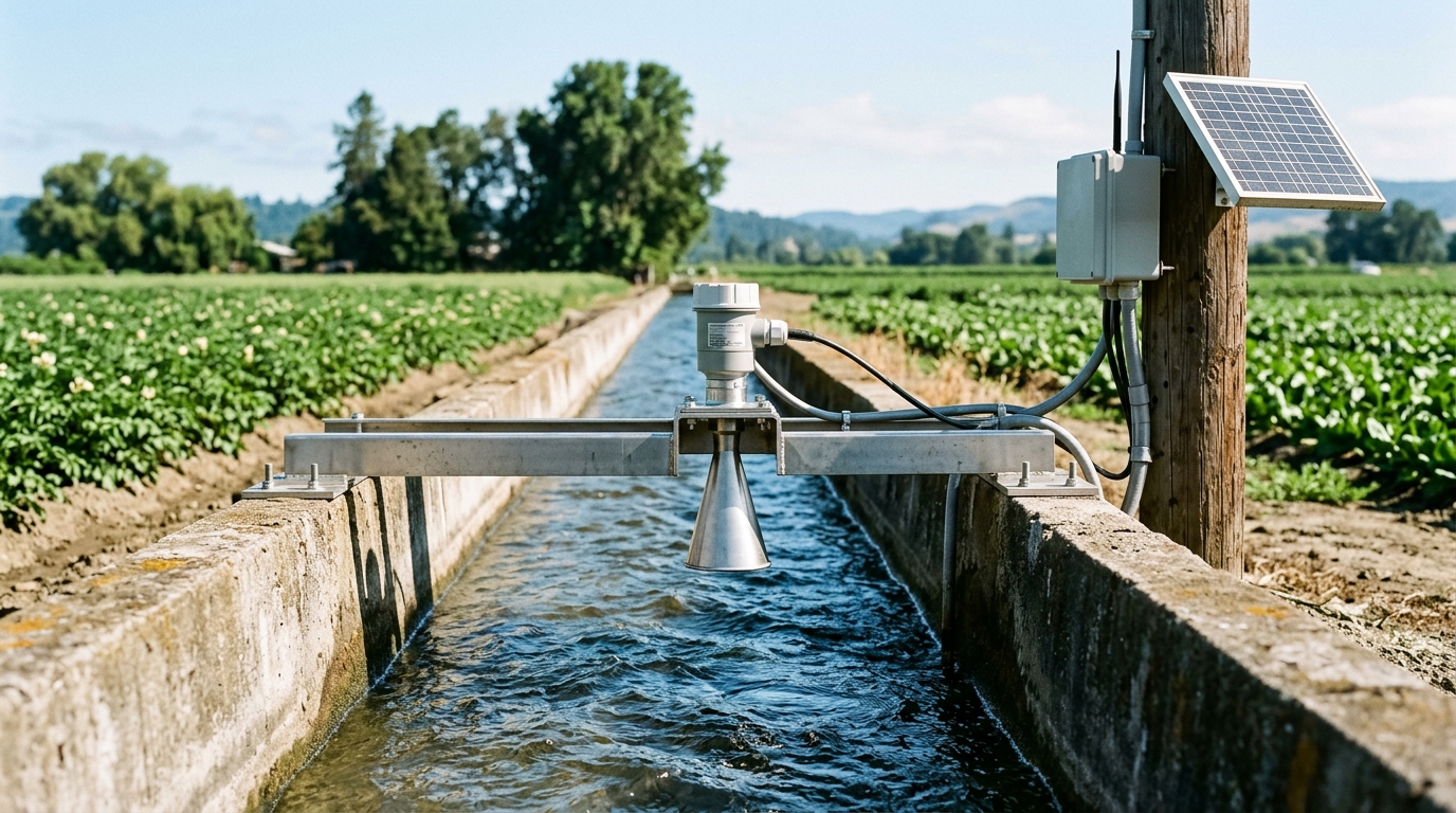
Open channels — defined as flow conduits with a free liquid surface — are ubiquitous in urban drainage ditches, agricultural irrigation canals, wastewater treatment outfall channels, and natural waterways. Unlike closed conduits, open channel flow cannot be directly computed as the product of cross-sectional area and velocity. Instead, flow rate must be inferred indirectly through a stage-discharge relationship (Rating Curve) or via standardized primary elements such as Parshall flumes, V-notch weirs, or broad-crested weirs.
Traditional contact-level instruments (float gauges, bubbler systems, submersible pressure transducers) face persistent challenges in open channel applications: sedimentation blockage, debris entanglement, and high maintenance frequency. In recent years, non-contact radar level transmitters have emerged as the preferred solution, offering simplified installation, maintenance-free operation, and robust interference rejection.
2. Special Requirements Imposed by Open Channel Environments
Compared with open water bodies (reservoirs, lakes), open channel environments present unique challenges that demand specific technical considerations:
- Narrow cross-section with strong sidewall reflections: Channel widths typically range from 0.5 m to 5 m. An overly wide radar beam may illuminate channel walls, generating false echoes that cause measurement jumps.
- Complex surface wave patterns: Gate operations and upstream flow variations create standing waves, surges, and turbulent conditions, demanding advanced signal processing capabilities.
- Harsh environmental conditions: Drainage channels frequently contain corrosive gases (H₂S, CH₄), grease films, and foam debris, imposing stringent requirements on antenna material and ingress protection rating.
- Constrained installation geometry: Urban manholes and small flume installations have limited mounting height, necessitating radar models with short range and minimal dead band.
3. Selection Criteria: Frequency, Antenna, and Signal Processing
3.1 Frequency Selection
Current radar level transmitters operate across three primary frequency bands, each suited for different scenarios:
6–10 GHz (Low Band)
Beam angle ~15°–20°. Suited for open water bodies; not recommended for narrow channels due to sidewall interference.
26 GHz (Mid Band)
Beam angle ~8°–10%. The mainstream choice for open channel applications, balancing measurement accuracy with interference rejection at an attractive price point.
80 GHz (High Band)
Beam angle compressed to 3°–4°. Ideal for narrow channels with severe interference issues.
Engineering Recommendation:
- For channel width >2 m, prefer 26 GHz.
- For width <2 m, consider 80 GHz for superior directivity.
3.2 Antenna Type
- Parabolic antenna: Excellent directivity for clean water surfaces; performance degrades significantly when surface contamination accumulates.
- Planar array antenna: Flush-mounted, no protruding structures, resistant to material buildup; ideal for grease-laden or foamy wastewater channels.
- Drip (drop) antenna: Compact form factor with minimal dead band; suited for manhole installations with restricted headroom.
3.3 Signal Processing Algorithms
Surface turbulence in open channels broadens the echo return signal. Quality radar transmitters should provide:
- Multi-echo tracking: Discriminates the true water surface echo from fixed obstructions (brackets, channel walls).
- Adaptive filtering: Automatically adjusts filter parameters based on surface turbulence intensity, balancing response speed against stability.
- False Echo Mapping (FEM): After installation, performs a reference scan to store the echo signature of fixed obstructions, which are then suppressed in subsequent measurements.
4. Installation Standards and Commissioning Procedures
4.1 Location Selection
- Mount the radar transmitter in a straight upstream section (≥10× channel width) of the primary element to ensure laminar flow conditions.
- Avoid positions directly above inlet structures or downstream of gates where surface turbulence is severe.
- Maintain antenna-to-wall distance ≥ 1/4 of channel width to minimize sidewall reflections.
4.2 Mounting Height and Alignment
Mounting height must satisfy the radar's dead band requirement (26 GHz: typically 0.3 m; 80 GHz: as low as 0.05 m). The antenna must be perpendicular to the water surface with tilt not exceeding ±2°. For sloped channels, use adjustable-angle mounting brackets.
4.3 Field Commissioning Sequence
- Dry-channel reference scan: With the channel empty, perform a full-range scan to record echo signatures of the channel bottom and walls.
- False Echo Mapping: Activate FEM to learn and store the fixed obstruction echo profile.
- Level verification: Compare radar readings against a reference measurement (steel tape or Vernier caliper) at known water levels. Acceptable tolerance: ≤±3 mm (Grade 1 accuracy) or ≤±5 mm (Grade 2 accuracy).
- Dynamic response test: Simulate rapid level changes (gate opening/closing) and observe tracking response; adjust filter time constants as needed.
5. Ingress Protection and Communication Interfaces
For open channel installations, a minimum IP67 protection rating is recommended; IP68 (continuous submersion) is advised for drainage network environments. In corrosive gas atmospheres, antenna material should be PTFE or PP, with 316L stainless steel housings.
The standard communication interface combination is 4–20 mA + RS-485 (Modbus RTU), interfacing directly with RTU telemetry units. For new smart water projects, consider integrated radar level transmitters with NB-IoT/4G wireless connectivity to reduce cabling costs.
6. Summary
Reliable water level acquisition is the cornerstone of open channel flow monitoring. Radar level transmitter selection must balance four dimensions: channel width, water quality conditions, installation geometry, and communication requirements. The 26 GHz radar serves most conventional open channel applications, while 80 GHz radar excels in narrow channels and complex conditions. Rigorous installation practices and systematic field commissioning — including straight-run compliance, dead band verification, and false echo mapping — are essential to fully realize the advantages of non-contact measurement technology.