In-Depth Comparison of Four Technical Approaches for Radar Water Level Meters
Water level is a fundamental parameter in water resource dispatching, urban waterlogging early warning, reservoir safety monitoring, industrial process control, and environmental discharge management. In the past, water level monitoring focused more on "whether data were available"; now, with the development of sensors, communications, edge algorithms, and digital twin platforms, the industry's focus has shifted to "whether data are accurate, stable, and capable of reflecting water surface changes in real time."
Among the various technology paths, radar water level gauges have become an important choice for rivers, reservoirs, urban drainage, channels, storage and regulation basins, and industrial tanks, thanks to non-contact measurement, adaptability to complex water surfaces, and relatively low maintenance requirements. In particular, 80 GHz radar (typically referring to 80 GHz high-frequency radar water level gauges) has attracted considerable attention in certain high-accuracy real-time monitoring scenarios because of its shorter wavelength, smaller beam angle, and higher range resolution. This article compares 80 GHz radar, low-frequency radar, ultrasonic, laser, pressure-type, float/guided-wave, and other technology paths from the perspectives of technical principles, key parameters, typical application scenarios, operations and maintenance costs, and selection logic, providing a reference for technology selection in water resource, municipal, environmental protection, and industrial monitoring projects.
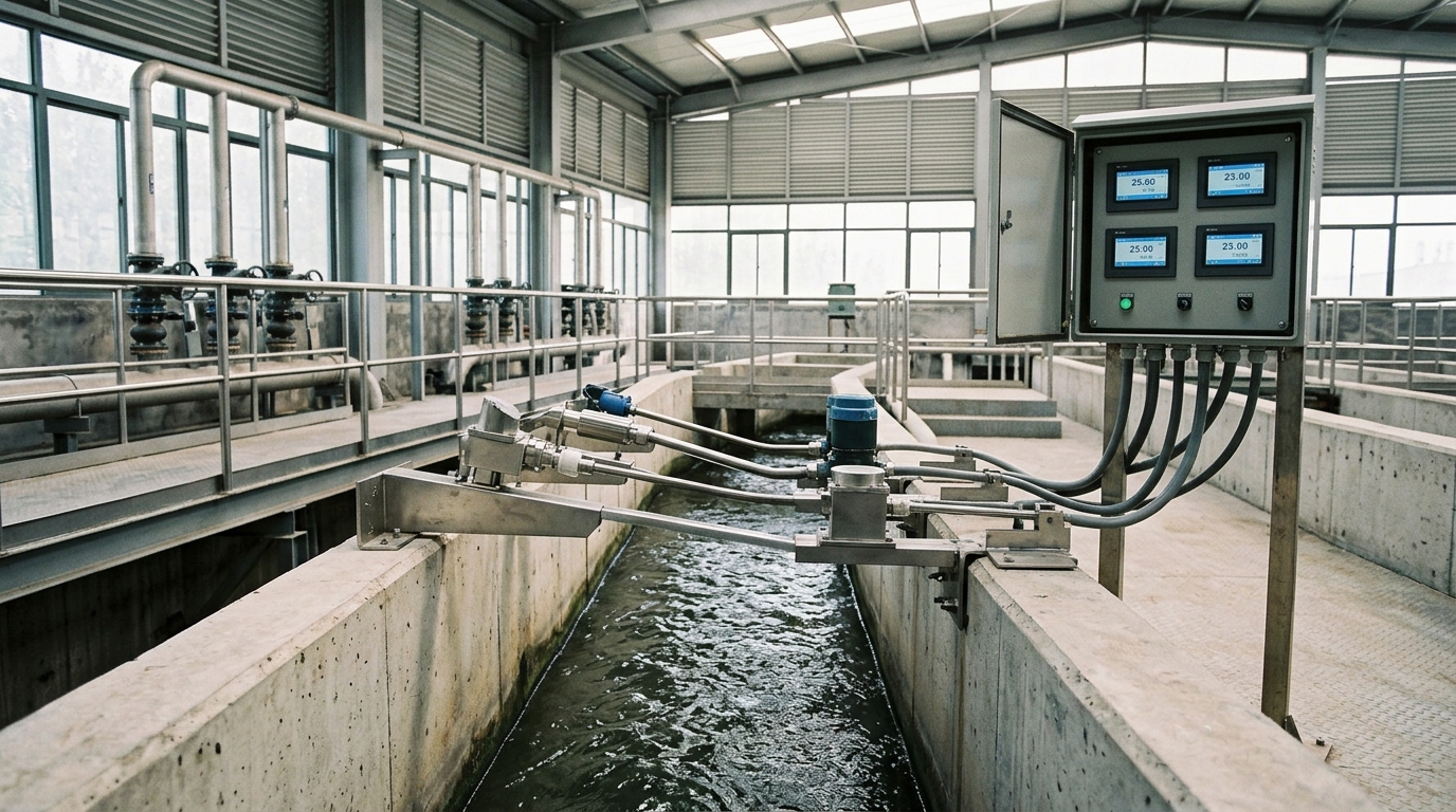
1. Water Level Monitoring Technology Paths: From Contact to Non-Contact
Technology paths for water level gauges can be broadly divided into two categories: contact and non-contact. Contact instruments typically place the probe, float, waveguide rod, or pressure diaphragm directly in the measured medium, and obtain liquid level or water level through medium pressure, buoyancy, changes in guided-wave signals, or mechanical displacement. Their advantages include intuitive principles, relatively low cost for some solutions, and high reliability in closed tanks or stable wells. However, contact solutions also face problems such as medium contamination, corrosion, scaling, blockage, jamming, and frequent maintenance. In particular, when the water flow contains sediment, floating debris, oil, foam, or chemically corrosive media, the condition of the probe directly affects measurement stability.
Non-contact instruments are not directly immersed in the water body or medium. Instead, they measure the distance from the sensor to the water surface by means of electromagnetic waves, ultrasonic waves, lasers, or image recognition, and then convert the measurement to water level based on installation height, datum plane, or radar profile. The core value of non-contact paths is reducing contact between the medium and sensing elements, thereby lowering contamination and wear. They are suitable for open water surfaces, flowing water, turbid water, hazardous media, and points requiring long-term online monitoring. However, non-contact solutions are not "install and forget." Their accuracy and stability are affected by installation angle, water surface fluctuation, steam, foam, rain and fog, dust, sidewall echoes, communication latency, and algorithm filtering. Therefore, selecting a technology path is essentially not a simple comparison of "whether non-contact is better than contact," but a comparison of overall suitability under different constraints of medium, range, accuracy, environment, operation and maintenance, and budget.
2. 80 GHz Radar Water Level Gauge: High Frequency & Precision
80 GHz radar water level gauges typically operate near the 80 GHz band, corresponding to an electromagnetic wavelength of approximately 3.75 mm. Compared with lower-frequency radars such as 26 GHz and 10 GHz, 80 GHz radar can more easily form a narrower beam with the same antenna size. Common beam angles are approximately 6° to 8°, and some structures can be even narrower. A smaller beam angle means a more concentrated measurement area, which helps reduce interference echoes generated by sidewalls, bridge piers, pipes, guardrails, vegetation, or well walls. This provides installation advantages in narrow channels, pipe shafts, spillways, and cross-sections under bridges. At the same time, high-frequency radar has higher range resolution, which helps capture subtle changes on the water surface. Some products specify accuracy of ±1 mm to ±2 mm, with repeatability controlled within ±1 mm to ±3 mm, depending on range, water surface condition, installation method, and algorithms.
"For urban waterlogging, flood early warning, and gate dispatching scenarios, a high sampling rate itself does not equal effective accuracy. The key is whether the instrument can maintain stable echoes when rainfall intensity increases, the water surface fluctuates, floating debris passes, or steam and foam change."
In terms of real-time monitoring, the measurement cycle of 80 GHz radar can usually reach millisecond or sub-second levels. Coupled with sampling frequencies of 1 Hz, 2 Hz, or higher, it can output continuous water level curves. 80 GHz radar is relatively sensitive to water surface reflection signals and is generally suitable for clean water, wastewater, turbid water, and environments with small amounts of foam or steam. However, in severe splashing, thick foam layers, strong rain curtains, large installation-angle deviations, or multiple reflections, waveguide tubes, shields, mounting brackets, filtering algorithms, and edge false-echo rejection are still required to ensure data quality.
The "non-contact" characteristic of 80 GHz radar provides certain maintenance advantages. Because the probe is not immersed in the water body, sludge attachment, corrosion, blockage, and mechanical wear are reduced, making it suitable for long-term unattended sites. However, high-frequency radar is more sensitive to installation conditions: the smaller the beam angle, the higher the requirements for verticality, horizontality, and obstruction-free space in front of the antenna. In actual projects, an installation error exceeding 1° to 2° can cause obvious pointing deviation at a 30 m range. If metal brackets, bridge piers, diversion walls, or well-wall protrusions are present in front of the antenna, interference echoes may be generated. Therefore, 80 GHz radar is more suitable for sites with standardized installation, stable brackets, clear measurement paths, and reliable data links. Common configurations include RS485, 4–20 mA, SDI-12, NB-IoT, 4G, LoRa, and other output methods. Protection ratings are mostly IP67 or IP68, and operating temperature ranges can cover -40°C to 70°C, but extreme environments still require comprehensive assessment of power supply, lightning protection, thermal insulation, and communication conditions.
3. Low-Frequency Radar vs. 80 GHz Radar: Boundaries of Electromagnetic Waves
Common operating frequency bands for low-frequency radar water level gauges include 26 GHz, 10 GHz, and others. Their wavelengths are relatively longer; for example, 26 GHz corresponds to a wavelength of approximately 11.5 mm, and 10 GHz corresponds to approximately 30 mm. The advantage of low-frequency radar is that its beam angle is usually larger, resulting in higher installation tolerance and lower sensitivity to antenna pointing, slight bracket deformation, water surface fluctuation, and local obstacles. Some low-frequency radar products specify accuracy of ±3 mm to ±5 mm and ranges of 20 m to 30 m, and still offer good cost-effectiveness in open water surface scenarios such as rivers, reservoirs, and channels. For projects such as general hydrological monitoring, drainage network level monitoring, and storage and regulation basin water level control, where millimeter-level accuracy is not stringent, low-frequency radar is often a more prudent choice.
The core difference between 80 GHz radar and low-frequency radar lies in "accuracy potential" and "installation requirements." Under ideal installation conditions, 80 GHz radar can more easily achieve higher range resolution and less beam interference, making it suitable for scenarios that are sensitive to water level changes, require capture of fine fluctuations, or have narrow measurement spaces. However, 80 GHz radar is not superior to low-frequency radar at all sites. If field brackets are unstable, installation angles are difficult to calibrate, or there are large amounts of floating debris or rain-curtain interference on the water surface, an excessively narrow beam may instead increase the risk of echo loss or false echoes. Because low-frequency radar has a wider beam, it is more tolerant of installation errors and water surface disturbance, making it suitable for projects with limited budgets, average maintenance capabilities, and accuracy requirements at the centimeter or sub-centimeter level. When selecting technology, one should not look only at specified accuracy, but should judge based on field installation conditions, data links, maintenance cycles, and total lifecycle cost.
4. Ultrasonic, Laser, and Vision: Complementary Strengths
Ultrasonic: Ultrasonic water level gauges emit sound waves and receive echoes from the water surface to measure distance, representing a common non-contact solution. Their cost is relatively friendly and installation is simple. Ranges are typically between 0.3 m and 10 m, with common accuracy of ±3 mm to ±10 mm or 0.25% to 1% of full scale. However, ultrasonic measurement depends on propagation through air, and the speed of sound is significantly affected by temperature, humidity, and atmospheric pressure. For every 1°C change in temperature, the speed of sound changes by approximately 0.6 m/s, so temperature compensation is required. Strong wind, rain and fog, steam, dust, foam, and severe water surface fluctuation can weaken echoes or cause misjudgment. In wastewater treatment plant aeration tanks, sludge tanks, and industrial tanks containing large amounts of foam or steam, ultrasonic measurement may exhibit data jumps due to surface scattering or absorption. For short-range scenarios such as urban waterlogging on roads, ultrasonic technology can serve as a low-cost supplement, but its stability under severe weather and complex medium conditions is inferior to that of high-frequency radar.
Laser: Laser water level gauges use laser ranging principles, commonly time-of-flight or phase-shift methods, and can achieve accuracy of ±1 mm to ±5 mm over ranges from several meters to tens of meters. The advantages of laser include strong directionality, fast response, and suitability for high-accuracy ranging. Its weaknesses are equally obvious: rain, fog, dust, steam, water surface reflection, and strong illumination can all affect laser echo quality. In open rivers, reservoir spillways, and similar scenarios, rain curtains and spray may cause data interruptions. Laser devices also involve eye-safety classes and on-site protection requirements. For closed or semi-closed, clean, and stable measurement environments, laser is one of the high-accuracy solutions; for long-term exposure to rainwater, sediment, and floating debris in hydraulic sites, a more cautious assessment is required.
Vision: Vision water level gauges use cameras to capture staff gauges, scale markings, or water surface boundaries, and then convert images to water level through image recognition. Their advantage is that the equipment is relatively intuitive and can simultaneously provide video evidence and image data, making them suitable for integration with urban governance and flood-control video platforms. However, vision solutions are significantly affected by illumination, nighttime supplemental lighting, rain and fog, lens contamination, water surface reflection, staff gauge occlusion, and calibration accuracy. Common accuracy is ±1 cm to ±5 cm, making it difficult to meet millimeter-level real-time control requirements. Vision is more suitable for auxiliary inspection, alarm verification, data traceability, and platform display, rather than serving as the sole high-accuracy water level measurement instrument.
5. Pressure-Type, Float, and Guided-Wave: Contact Solutions
Pressure-type water level gauges convert hydrostatic pressure of the water body into water level. The principle is P = ρgh, where ρ is medium density, g is gravitational acceleration, and h is liquid level height. The hydrostatic pressure of a 1 m water column is approximately 9.8 kPa, so pressure-type instruments are widely used in wells, tanks, basins, and pipelines. Their advantages include ability to measure high liquid levels, fast response, and stable output. Some products achieve accuracy of 0.1% FS or within ±0.5 cm, making them suitable for closed or semi-closed environments. However, pressure-type solutions must contact the water body, and the probe is easily affected by sludge, grease, algae, sediment, corrosive media, and microbial attachment. In scenarios such as rainwater wells, wastewater networks, and river intake structures, regular cleaning or replacement is required. Pressure-type measurement also relies on vent tubes for atmospheric pressure compensation; if the vent hole is blocked or the cable venting performance degrades, significant errors may occur.
Float-type water level gauges are traditional mechanical solutions. As the float rises and falls with the water surface, it drives an encoder, wire rope, or mechanical transmission to output water level. Their structure is simple, reliability is high, and maintenance experience is mature, making them suitable for hydrological stations, reservoirs, gates, and stable water bodies. However, float solutions are subject to mechanical wear, jamming, wire rope fatigue, icing, entanglement by floating debris, and long-term calibration drift. In environments containing large amounts of sediment, garbage, oil, or ice, a higher maintenance frequency is required. Guided-wave radar or magnetostrictive level transmitters are more commonly used in industrial tanks, suitable for closed media and precise level control. However, for open water surfaces, floating debris, and violently fluctuating hydraulic scenarios, the waveguide rod may be subjected to collision, entanglement, and contamination, and installation conditions are also relatively constrained.
Contact solutions are not outdated technologies. In scenarios such as closed shafts, stable media, low maintenance budgets, short ranges, or requirements for direct pressure data, pressure-type and float-type gauges still have advantages. For points requiring long-term unattended operation, turbid media, significant water surface fluctuation, and limited maintenance access, non-contact radar often better reduces operation and maintenance burden. A common practice in actual projects is "non-contact as primary, contact as backup." For example, a river cross-section may use 80 GHz radar or low-frequency radar, supplemented by pressure-type or vision measurement for anomaly validation, thereby improving data credibility.
6. Typical Scenario Cases: Selection Logic
Urban Waterlogging
For urban waterlogging road-flooding monitoring, the range is usually short (0-30 cm), and accuracy requirements are mostly ±1 cm to ±3 cm. The key is uninterrupted data during heavy rainfall.
In one city's pilot site, an 80 GHz radar installed on a pole maintained a continuous curve under 40 mm/h rainfall, proving more stable than ultrasonic measurement under rain-curtain interference. Pressure-type solutions in wells are easily blocked; vision suffers at night.
Rivers & Reservoirs
Ranges reach 5-15 m. Disturbances include fluctuation, debris, and sidewall echoes.
An 80 GHz radar in a measuring shaft under a bridge, using a waveguide tube, achieved ±2 cm deviation from manual readings during floods. While 26 GHz radar offers ±5mm-±1cm accuracy sufficient for general monitoring, 80 GHz excels in refined dispatching. Ultrasonic struggles with wind/fog; pressure probes get contaminated by sediment.
Industrial Media: In wastewater treatment plants, chemical storage tanks, and industrial process control scenarios, medium conditions are more complex. In a project with a 5-10 cm foam layer, ultrasonic failed due to insufficient echo strength, and pressure probes got coated with sludge. Switching to 80 GHz radar improved stability significantly, extending maintenance cycles from weeks to months. For strongly corrosive or hazardous areas, non-contact radar reduces probe contact risks, but explosion-proof certification and corrosion-resistant housings are mandatory.
7. Selection Recommendations: Parameters Back to the Field
- Clarify Environment First: Don't just pick the highest accuracy. Confirm range, medium type, fluctuation, foam/steam presence, corrosive substances, installation space, power, communication, and maintenance access.
- Distinguish Instrument vs. System Accuracy: Specified ±1 mm doesn't mean field ±1 mm. Account for installation datum, temperature, latency, platform conversion, and bracket vibration. Include all these in your accuracy budget.
- Assess Installation Conditions: 80 GHz requires perpendicular alignment and obstruction-free space. Use waveguide tubes/shields in narrow spaces. If brackets vibrate or angles are hard to calibrate, consider low-frequency radar.
- Select Communication Architecture: Wired for fixed sites; NB-IoT/4G/LoRa for dispersed points. Real-time monitoring requires edge filtering, outlier rejection, retransmission, and time synchronization to close the loop for flood early warning.
- Estimate Total Lifecycle Cost: Include purchase, installation, brackets, comms, power, cleaning, spare parts, calibration, and downtime losses. Non-contact radar may have higher initial cost but lower O&M in turbid/unattended sites.
8. Outlook: Edge Intelligence & Multi-Source Fusion
The future of radar water level gauges will emphasize field adaptability and data credibility over just frequency or spec sheets. 80 GHz, 26 GHz, ultrasonic, laser, pressure, and vision will form a complementary system. High-frequency radar suits refined monitoring; low-frequency remains competitive for cost/tolerance; pressure serves closed shafts; vision provides evidence chains.
Edge Intelligence: Gauges will perform waveform recognition, false-echo rejection, and fluctuation filtering locally. For 80 GHz, this helps distinguish true water surface from rain curtains, foam, and debris. Multi-Source Fusion: Linking radar with pressure, vision, meteorological, and gate position data improves robustness when single sensors fail. Urban waterlogging and flood dispatching increasingly demand this cross-validation.
Standardization: The industry needs unified installation specs, accuracy verification, data protocols, and drift assessments. Successful selection depends on matching the technology path to the application boundary, rather than simply pursuing higher frequency or lower price. For 80 GHz radar, its value lies in providing feasible solutions for complex water surfaces, narrow spaces, and high-accuracy real-time monitoring. Rational comparison and standardized engineering are the foundation for improving water level monitoring quality.

