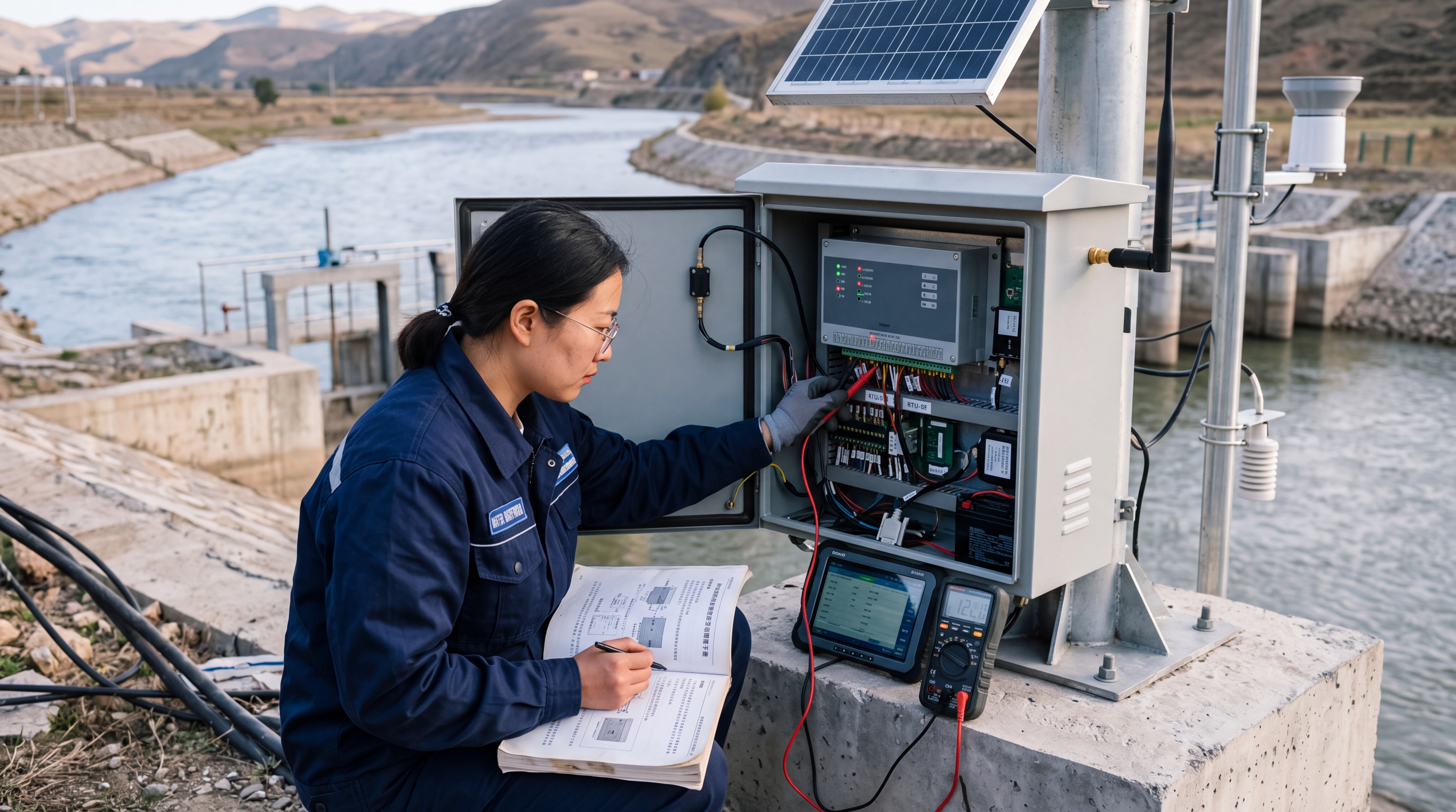
Introduction: From "Installation" to "Stable Operation": Practical RTU Competence Becomes Key to Water Monitoring
In scenarios such as water conservancy monitoring, irrigation district scheduling, river water level observation, rainfall observation, pump station control, and reservoir safety monitoring, the RTU telemetry terminal plays a pivotal role as the hub for on-site data acquisition, local storage, remote transmission, alarm reporting, and interlocked control. Compared to early manual meter reading or single data transmission devices, RTUs must simultaneously address multiple challenges, including complex sensor types, limited power supply conditions, unstable communication environments, and the need for highly reliable operation during flood seasons. To help frontline engineering personnel establish standardized operating procedures, this article uses the Yicai Technology Hero V9 telemetry terminal as an example to compile a practical, implementable guide covering pre-installation preparation, on-site installation steps, commissioning methods, data acquisition and remote transmission configuration, routine maintenance, and common troubleshooting.
The parameters in this article are based on typical water monitoring stations, encompassing the integration of devices such as solar power supplies, 4G or BeiDou transmission modules, water level gauges, rain gauges, flow meters, pressure transmitters, and gate position indicators. In actual projects, standardized installation and commissioning can significantly reduce subsequent O&M pressure. For example, after standardized upgrading of 216 monitoring stations in a certain river basin, with the acquisition cycle set to 5 minutes and the regular reporting cycle to 15 minutes, flood season alarm information can reach the platform within 1 minute, and the monthly data integrity rate is maintained above 99.7%. The goal of this article is not to replace the equipment manual, but to provide a set of on-site executable checklists, parameter setting methods, and troubleshooting paths, helping engineering personnel elevate the RTU from merely "installable" to "stably operable, maintainable, and traceable."
Pre-Installation Preparation: Clarify Site Conditions, Interface Inventory, and Risk Points First
The installation quality of an RTU largely depends on preliminary preparation. It is recommended to complete three tasks before installation: site survey, material verification, and risk contingency planning. The site survey should clarify the RTU enclosure installation location, power supply method, antenna placement, sensor cabling routes, lightning protection and grounding conditions, and communication signal strength. Common environments at water conservancy sites include riverbanks, dam crests, gatehouses, pump stations, canal edges, and wilderness poles. Installation locations should avoid low-lying waterlogged areas, strong electromagnetic interference, falling rocks, scouring, and areas prone to vandalism. If installation in a low-lying area is unavoidable, the enclosure height should be increased, with drip loops and drainage measures implemented.
Taking the Hero V9 as an example, common configurations include multiple analog inputs, digital inputs, relay outputs, RS485 interfaces, Ethernet interfaces, and 4G communication, with the option to expand with BeiDou short message or short-range wireless transmission modules based on project requirements. Before installation, verify that the interfaces meet the sensor requirements. For instance, water level gauges commonly use 4-20mA or RS485 outputs; rain gauges typically use pulse or digital outputs; flow meters may use Modbus RTU; pressure transmitters usually use 4-20mA; and gate position indicators may output analog or encoder signals. If interfaces are insufficient, expansion modules should be added or the acquisition scheme adjusted in advance to avoid on-site rewiring.
Material preparation should include the RTU host, mounting brackets, waterproof enclosure, solar panels, batteries, charge controllers or power modules, antennas, feeder cables, SIM cards or BeiDou communication modules, RS485 shielded twisted pair cables, signal wire terminals, fuses, surge protectors, grounding copper bars, grounding electrodes, waterproof tape, heat shrink tubing, identification tags, and cable ties. For tools, it is recommended to prepare a multimeter, clamp meter, ground resistance tester, laptop or on-site configuration terminal, serial port tools, network cables, tape measure, spirit level, torque wrench, and camera for photographic records.
Communication signal testing should also be conducted before installation. For 4G sites, it is recommended to use a mobile phone or signal testing device to read the signal strength. The general acceptable reference values are RSRP no lower than -95dBm and SINR no lower than 5dB; if the signal is weaker than -105dBm, high-gain antennas, external antennas, directional antennas, or a BeiDou backup link should be evaluated. For critical water conservancy stations, a "4G primary link + BeiDou short message backup" approach is recommended to ensure critical alarms can still be uploaded if the primary network is interrupted. Regarding safety, operations involving water proximity, heights, live electricity, and thunderstorms must strictly adhere to power-off and voltage verification, anti-slip and fall protection, lightning protection and avoidance, and a two-person work system.
Installation Steps: Implement Power Supply, Wiring, Antenna, Grounding, Waterproofing, and Labeling Step by Step
The first step is to determine the installation location and mounting method. The Hero V9 or similar RTUs are generally recommended to be installed inside a waterproof enclosure. The enclosure mounting height should be above the historical maximum water accumulation level, the door should be easy to open for maintenance, and cable entry holes should face downward to prevent rainwater from flowing back along the cables. When mounting on a pole, the pole foundation must be stable, and the enclosure clamps must be tightened to prevent swaying in strong winds. If installed in a gatehouse or pump house, choose a well-ventilated, dry location with minimal vibration, and keep away from high-power inverters, motors, and high-voltage busbars.
The second step is the power system installation. Solar panels combined with batteries are commonly used for power supply in wilderness water conservancy sites. Taking a typical low-power RTU site as an example, if the average device power consumption is 1W to 3W, with a daily acquisition cycle of 5 minutes and a reporting cycle of 15 minutes, a common configuration is a 30W to 100W solar panel and a 20Ah to 65Ah battery; sites with higher requirements for continuous cloudy or rainy days can be calculated based on 5 to 7 days of autonomy. Batteries should be placed in a dedicated battery box to avoid sun exposure and water immersion. When wiring, connect the battery first, then the solar panel, and finally power on the RTU to prevent no-load voltage surges. Fuses and reverse-polarity protection should be installed at the power input terminal. For a 12V system, it is recommended to keep the operating voltage range between 11.0V and 14.4V, and check accordingly for a 24V system.
The third step is sensor wiring. Analog inputs commonly use 4-20mA or 0-5V signals; before wiring, confirm that the sensor power supply matches the RTU interface. For 4-20mA loops, ensure the load resistance meets the transmitter requirements. The typical load capacity of common transmitters is 0 to 500Ω; if the line is too long or too many instruments are connected in series, the total load must be calculated. RS485 buses should use shielded twisted pair cables with a wire diameter of no less than 0.5mm², and the length of a single bus should generally not exceed 1000 to 1200 meters. The baud rate, data bits, parity bit, and stop bit of devices on the same bus must be identical. The shield layer should be grounded at one end only to avoid ground loops. For pulse rain gauges, pay attention to the polarity of the reed switch or digital output and the debounce settings to prevent a single rainfall event from being counted multiple times.
The fourth step is antenna and communication module installation. 4G antennas should be installed in open areas as much as possible, avoiding obstruction by metal enclosures. External suction cup antennas or fiberglass antennas should be mounted higher than surrounding obstructions. The bending radius of the feeder cable should not be too small, and connectors must be waterproofed. If a BeiDou module is used, the antenna must have a clear view of the sky, avoiding obstruction by trees, buildings, or metal structures. The feeder cable length between the antenna and the RTU should be kept within a reasonable range, as excessive length will increase signal loss. After installation, check the signal strength via the device status page or AT commands, and record the initial value for future comparison.
The fifth step is lightning protection and grounding. Wilderness RTU sites should establish an independent or joint grounding system. The grounding resistance is recommended to be no greater than 4Ω; in areas with high soil resistivity, it can be improved by adding grounding electrodes, using resistance-reducing agents, or installing a grounding grid. Corresponding surge protectors can be configured on the power, signal, and antenna feeder sides based on local lightning risk. Signal surge protectors should be installed before RS485 and analog signal lines enter the enclosure. The metal shell of the enclosure, brackets, solar panel frames, and surge protector grounding wires must be reliably connected to the grounding copper bar. The sixth step is waterproofing, rat-proofing, and labeling. All cable entry holes should use waterproof connectors, and any unused holes must be sealed. Desiccants can be placed inside the enclosure. Cables should be neatly tied and labeled with identification tags indicating the sensor name, wire number, destination, and wiring date. Upon completion, take photos for archival and generate a site installation record form.
Commissioning Methods: Forming a Closed Loop from Local Configuration and Communication Links to Data Calibration
Before commissioning, a static check should be performed first: confirm that the power polarity, battery voltage, solar panel open-circuit voltage, sensor power supply, RS485 A/B lines, antenna connectors, and grounding connections are all correct. The first power-on is recommended to be done in stages: first disconnect the sensor loads and power on only the RTU, observing whether the power, operation, and communication indicator lights are normal; then connect the communication module, and finally connect the sensors one by one. This avoids whole-machine anomalies caused by single-point wiring errors.
Local configuration can be completed via serial port, Bluetooth, Ethernet port, or local configuration tools. Taking the Hero V9 as an example, commissioning personnel typically need to set the device ID, station name, acquisition tasks, communication parameters, server address, reporting strategy, and alarm rules. It is recommended to adopt a unified coding rule for device IDs, such as "Basin Code-Station Type-Sequence Number," to facilitate platform identification and subsequent O&M. Regarding communication parameters, if using a 4G network, configure the APN, username, password, server IP or domain name, port, heartbeat interval, and reconnection strategy; if using a hydrological industry platform, also configure the hydrological protocol, station code, password, and reporting protocol as required by the platform.
Acquisition parameter setting is the core of commissioning. For Modbus RTU sensors, it is necessary to configure the slave address, baud rate, data bits, parity bit, stop bit, function code, register address, data type, and unit conversion. Common settings are a baud rate of 9600 or 19200, 8 data bits, N parity, and 1 stop bit; if the sensor factory parameters differ, the sensor manual shall prevail. The acquisition cycle should be set according to business requirements. Routine water monitoring can adopt a 5-minute acquisition and 15-minute reporting cycle; during flood seasons or alarm states, this can be shortened to 1-minute acquisition and immediate reporting. To reduce data consumption, threshold-based reporting can be set, for example, immediately reporting when the water level changes by more than 1cm, accumulated rainfall exceeds 0.5mm, or battery voltage drops below a threshold.
Data calibration must not be omitted. When commissioning a water level gauge, manually read the staff gauge or a known elevation point on-site and compare it with the RTU acquisition value; the error should be controlled at the centimeter level. For pressure-type water level gauges, confirm the zero point, span, and local atmospheric pressure compensation. When commissioning a flow meter, verify the flow velocity, cross-sectional area, and cumulative flow coefficient, and conduct on-site comparative measurements if necessary. Rain gauges are commonly of the tipping-bucket type, with resolutions typically of 0.2mm or 0.5mm. During commissioning, perform a manual water pouring test to check if the tipping bucket action, pulse counting, and platform accumulation are consistent. Gate position indicators or opening meters should be calibrated at three positions: fully closed, half-open, and fully open, to avoid linear errors.
Remote transmission commissioning should verify that data is "acquired, stored, transmitted, and correctly parsed by the platform." Focus on checking four items: first, whether the device successfully connects to the server, and whether the MQTT, TCP, or hydrological protocol link is stable; second, whether the data fields received by the platform are correct, including timestamps, water level, rainfall, flow, voltage, signal strength, and device status; third, whether breakpoint resume is effective, which can be tested by disconnecting the network on-site for 10 to 30 minutes and checking if historical data is retransmitted upon recovery; fourth, whether alarm reporting is timely, which can be tested by artificially simulating water level exceeding the threshold, low battery, or device offline, to see if the platform generates alarms. It is recommended that new stations enter a 72-hour trial operation after commissioning, recording the online rate, data integrity rate, false alarm situations, and battery voltage changes before formal handover.
Data Acquisition and Remote Transmission: Ensuring Water Conservancy Data is Complete, Accurate, and Traceable
The goal of data acquisition is not merely to "have data," but to ensure it is "accurate, continuous, and traceable." In water conservancy applications, RTUs often need to process analog, pulse, digital, and bus data simultaneously. To reduce on-site interference, it is recommended to configure basic data quality control rules at the RTU end, including range checking, sudden change filtering, dead value judgment, and wire break detection. For example, if the water level range is set to 0 to 10 meters, and the acquired value suddenly becomes -999, exceeds 15 meters, or remains unchanged for a long time, it should be marked as abnormal data and an alarm reported. Rainfall data can be checked for rationality based on the maximum minute rainfall intensity to avoid abnormal large values caused by interference.
The remote transmission protocol should be selected according to platform requirements. Common methods include MQTT, Modbus TCP, HTTP, hydrological industry protocols, and SMS or BeiDou short messages. For newly built platforms, MQTT is widely used due to its lightweight nature, low bandwidth consumption, and suitability for weak network environments. A topic structure of "Station ID/Data Type/Time" can be adopted, with the payload containing fields such as device ID, acquisition time, water level, rainfall, flow, battery voltage, signal strength, and alarm codes. If the platform uses a hydrological protocol, it must be strictly configured according to station coding, observation elements, time tags, and message formats to avoid platform parsing failures caused by errors in byte order, BCD code, CRC check, or time zone settings.
The communication strategy should balance real-time performance, data traffic costs, and battery life. Routine stations can adopt scheduled reporting combined with change-triggered supplementary reporting. Taking a 4G Cat.1 link as an example, if reporting occurs every 15 minutes, the monthly data traffic is usually low, but it still needs to be estimated based on message size, heartbeat frequency, and retransmission count. For low-power stations, the heartbeat interval can be set to 30 to 60 minutes; if the platform requires rapid perception of online status, the heartbeat can be appropriately shortened, but this will increase power consumption and data traffic. In weak network environments, it is recommended to enable local caching. The cache capacity should meet the data storage requirements during network disconnection, typically capable of storing thousands to tens of thousands of records, ensuring automatic retransmission once the network recovers.
Security and time synchronization are equally important. It is recommended to enable TLS encryption or platform authentication mechanisms for remote transmission to prevent data interception or illegal access. The device clock should be calibrated via NTP or platform-issued time synchronization. If BeiDou timing is used, check the time zone and time format to prevent an 8-hour deviation. For critical water conservancy stations, dual-link communication can be configured: the primary link is 4G, and the backup link is BeiDou short message or SMS. When the primary link fails consecutively beyond a set number of times, the device automatically switches to the backup link; it switches back after the primary link recovers, and logs the switch.
Taking a river water level and rainfall station as an example, the station integrates a radar water level gauge, a tipping-bucket rain gauge, and battery voltage monitoring. The water level range is 0 to 10 meters with a resolution of 1 centimeter; the rainfall resolution is 0.5 millimeters; the acquisition cycle is 5 minutes, regular reporting is every 15 minutes, and threshold exceedances trigger immediate reporting. After on-site configuration of the Hero V9, the platform can view the water level hydrograph, cumulative rainfall curve, device voltage, and communication status in real time. When the water level exceeds the warning value, the RTU reports the alarm within 1 minute and can interlock with on-site audible and visual alarms or notify relevant responsible personnel via relay output. The value of this model lies in converting scattered on-site data into dispatchable, analyzable, and accountable business information.
Routine Maintenance: Reducing the Probability of Sudden Failures Through Periodic Inspections and Data Comparison
RTUs operate in the wilderness for long periods, so the maintenance focus should shift from "repair after failure" to "preventive maintenance." It is recommended to establish a system of monthly remote inspections, quarterly on-site inspections, and pre-flood season special inspections. Remote inspections mainly check the device online rate, data integrity rate, battery voltage, solar charging voltage, signal strength, alarm records, and the time of the last report. If continuous offline status, data jumps, voltage anomalies, or a significant drop in signal strength are found, on-site verification should be arranged in advance to avoid missing critical data during the flood season.
On-site inspections should cover five aspects: enclosure, power supply, communication, sensors, and grounding. For the enclosure, check the door seal, latches, cable entry connectors, condensation, and pest infestation; replace aging seals promptly. For the power supply, check if the solar panel surface is obstructed by dust, bird droppings, or leaves, and if the bracket is loose; check if the battery terminals are oxidized and if the voltage is within the normal range. For lead-acid batteries in a 12V system, if the resting voltage is below approximately 11.8V or drops significantly under load, further check the capacity or replace the battery; for lithium battery stations, pay attention to the BMS status and charge/discharge records. The common float charging voltage for solar charge controllers can refer to 13.5V to 13.8V, subject to battery type and manufacturer requirements.
The communication section should check if the antenna is loose, the feeder cable is damaged, or connectors have water ingress, and record the signal strength. If the signal has dropped significantly from the initial value, investigate the antenna position, feeder cable loss, or carrier network changes. The sensor section should undergo visual inspection, terminal tightening, and data comparison. Water level gauges can be compared with manual staff gauges, and recalibrated if the error exceeds the allowable range; rain gauges should have their rain-receiving orifices and filters cleaned, and the tipping bucket checked for sticking; flow meters should be checked for probe attachments, cross-sectional changes, and parameter settings. For mechanical gate position indicators, check the wire rope, pulleys, and counterweights.
Maintenance records are crucial for subsequent fault analysis. It is recommended to establish an electronic archive for each station, recording the installation time, device ID, SIM card number, IP or domain name, sensor model, range, calibration records, inspection photos, fault handling, and maintenance suggestions. Firmware upgrades should be executed cautiously: back up configuration files before upgrading, confirm the upgrade package version and power supply stability; after upgrading, verify acquisition tasks, communication parameters, and historical data. For batch stations, it is recommended to verify on a test station first, then upgrade in batches, to avoid centralized risks caused by simultaneous network-wide changes.
Pre-flood season maintenance is particularly critical. Before the flood season, conduct a 72-hour continuous operation test on key stations, simulating power outages, network disconnections, sensor anomalies, and alarm reporting, to confirm normal platform reception, availability of backup communication, and sufficient battery life. For stations undertaking flood control dispatch tasks, prepare a spare parts kit, including power modules, fuses, antennas, terminals, waterproof connectors, spare batteries, and common sensors. Through standardized maintenance, many hidden dangers can be eliminated in the early stages of data anomalies, rather than passively handling them after communication is interrupted during the flood season.
Common Troubleshooting: Locate Issues Following the Five Steps of "Power, Communication, Acquisition, Data, and Execution"
RTU troubleshooting is recommended to follow the sequence of "power—communication—acquisition—data—execution" to avoid blindly replacing equipment. The first common fault is the device failing to come online. First, measure whether the RTU input voltage is normal and if the power indicator is on; then check if the SIM card is properly inserted, not in arrears, and if the APN is correct; then check the signal strength. If the signal is normal but it cannot connect to the platform, check the server address, port, protocol, device code, password, and firewall policies. If the platform shows the device frequently going online and offline, check the heartbeat interval, TCP keep-alive, power voltage drops, and antenna contact.
The second type of fault is unstable communication or packet loss. This manifests as intermittent platform data, reporting delays, or offline alarms. During troubleshooting, record changes in RSRP and SINR. If the signal is consistently below -105dBm, consider changing the installation location, raising the antenna height, or enabling backup communication. If the signal is good but packets are still lost, check the antenna VSWR, feeder connectors, power ripple, and enclosure grounding. Some sites have high-power equipment starting and stopping, which may cause transient interference; this can be resolved by adding power filters, isolation transformers, or adjusting wiring. For RS485 bus devices, an excessively long bus, missing termination resistors, or poor shield grounding can also lead to acquisition timeouts; disconnect devices in sections to locate the fault.
The third type of fault is data anomalies. Common manifestations include data at zero, full scale, fixed, excessive jumping, or incorrect units. If the measured current for a 4-20mA signal is close to 0mA, it may be due to sensor power loss, wire break, or transmitter failure; if it is close to or above 20mA, it may be out of range or incorrectly wired. When an RS485 sensor has no data, check the slave address, baud rate, parity bit, function code, and register address, and confirm if there is an address conflict with other devices. For water level data jumping, first check if the mounting bracket is shaking, if the sensor filtering parameters are enabled, and if there is interference from waves or floating objects on-site. When rainfall data is abnormally large, check if the tipping bucket is jittering, if the reed switch is sticking, and the debounce time settings.
The fourth type of fault is power supply anomalies. This manifests as disconnection at night or on cloudy days, rapid battery voltage drop, or abnormal solar charging voltage. First, check if the solar panel is obstructed, if the charge controller is working, and if the battery is aging. If the voltage is normal during the day but drops rapidly at night, it is usually due to insufficient battery capacity or abnormal load. Use a clamp meter to measure standby power consumption and check for extra loads or modules with continuous high power consumption. For faults after thunderstorms, focus on checking the status of fuses, power modules, surge protectors, and communication modules; if the device has water ingress, cut off power, dry it, replace seals, and confirm the extent of corrosion before powering on.
The fifth type of fault is abnormal relay or control output. For example, remote control of pumps, gates, or alarms fails to actuate. Check the DO output configuration, control permissions, platform command records, and on-site feedback signals. If the platform shows the command has been issued but there is no action on-site, check locally at the RTU whether the relay status changes; if the relay actuates but the load does not respond, check if the load power supply, contactor, wiring terminals, and load power are matched. For critical control outputs, it is recommended to set up an "command—execution—feedback" closed loop to avoid relying solely on a single command. By establishing a fault code table and handling records, the troubleshooting time for common issues can be shortened from hours to minutes, and it also helps the O&M team accumulate standardized experience.
Application Cases and Outlook: Standardized O&M Transforms RTUs from Devices into Water Conservancy Data Infrastructure
In an informatization upgrading project for a medium-sized irrigation district, 120 monitoring stations were deployed on-site, covering canal water level, gate opening, flow, rainfall, and pump station status monitoring. The project adopted the Hero V9 as the RTU telemetry terminal, integrating 4-20mA pressure transmitters, RS485 flow meters, pulse rain gauges, and gate opening sensors. The communication method was primarily 4G, with key gate stations configured with BeiDou short message backup. The acquisition cycle was set to 5 minutes, regular reporting to 15 minutes, and gate actions and water level exceedances triggered immediate reporting. After 8 months of system operation, the average monthly online rate of the stations reached 99.5%, the data integrity rate reached 99.7%, and the platform alarm response time was shortened from the original hourly level of manual patrol to the minute level.
A typical experience from this project is "standardized installation, checklist-based commissioning, and data-driven maintenance." During the installation phase, the project team uniformly required cable entry holes to face downward, grounding resistance to be no greater than 4Ω, RS485 shield layers to be grounded at one end, and solar panel tilt angles to be set according to local latitude, with photos archived for each station. During the commissioning phase, each station was required to complete signal strength recording, sensor comparison, breakpoint resume testing, and alarm simulation testing. During the maintenance phase, O&M personnel monitored battery voltage, signal strength, and integrity rate trends via the platform, proactively addressing multiple issues such as loose antennas, obstructed solar panels, and aging batteries, thereby avoiding data interruption during the flood season.
From an industry trend perspective, RTUs are evolving from single data remote transmission devices into edge computing nodes. Future water conservancy RTUs will take on more tasks such as local data cleaning, anomaly identification, image capture interlocking, video overlay, model early warning, and multi-protocol conversion. With the development of low-power communication, edge AI, and digital twin platforms, on-site equipment must not only complete data acquisition and remote transmission but also provide a higher-quality data foundation for flood forecasting, water resource dispatch, precise water allocation in irrigation districts, and engineering safety assessment. For engineering implementation teams, mastering standardized methods for installation, commissioning, maintenance, and troubleshooting is more important than simply pursuing equipment parameters. Only by solidifying on-site details can RTUs operate stably in complex water conservancy environments over the long term, truly becoming reliable data infrastructure.

