Correct Usage of RTU Telemetry Terminals Under Complex Working Conditions
In scenarios such as smart water management, modernization of irrigation districts, flash flood disaster monitoring, pumping station automation, and river hydrological observation, RTU telemetry terminals undertake the core tasks of on-site data collection, local storage, remote transmission, and equipment control. Compared to ordinary communication modules, RTUs must better adapt to complex environments characterized by unstable field power supply, fluctuating communication signals, lightning strikes and humidity, and extreme temperature variations.
This article uses the Hero V9 RTU telemetry terminal as the primary example to form a set of actionable practical methods focusing on installation steps, data collection configuration, remote transmission joint debugging, daily maintenance, and common fault troubleshooting.
Note: This guide is applicable to water monitoring points, irrigation district canals, pumping stations, river water level stations, and rainfall stations. Actual projects should be based on equipment nameplates, design documents, and platform requirements.
From engineering experience, the long-term stable operation of an RTU system depends not only on the equipment itself but also on installation craftsmanship, power supply design, communication links, sensor matching, and O&M mechanisms. A qualified RTU monitoring point should ensure data is collectible, status is monitorable, anomalies trigger alarms, network disconnections are buffered, and maintenance is traceable.
1. Pre-Installation Preparation: Translating Site Conditions into an Actionable Checklist
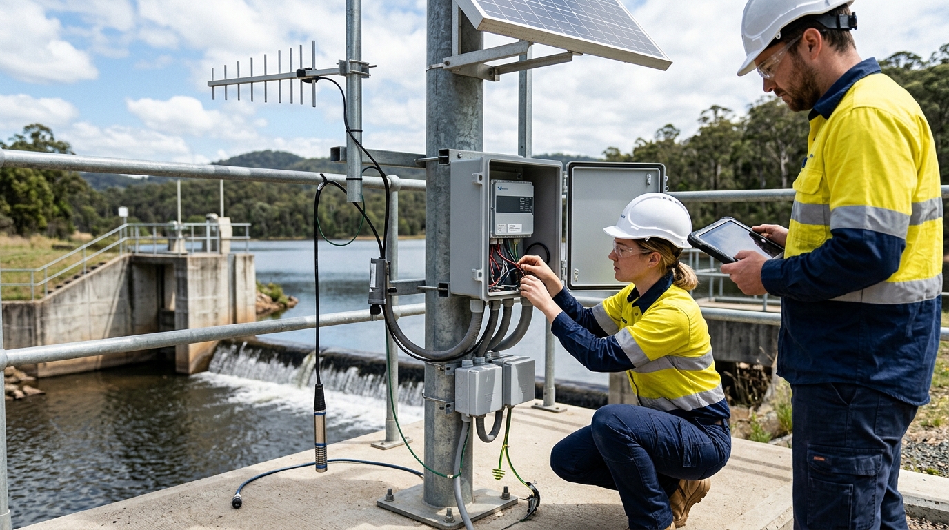
Pre-installation preparation is the most overlooked yet most impactful phase in an RTU project. Many subsequent failures are not due to equipment damage but to insufficient preliminary surveys, such as solar panels being shaded by trees, weak 4G signals, mismatched sensor interfaces, or missing lightning protection grounding. For integrated RTU telemetry terminals like the Hero V9, it is recommended to confirm five aspects before installation: monitoring objects, power supply conditions, communication conditions, interface resources, and protection requirements.
- Monitoring Objects: Clearly define data items (e.g., water level, flow rate, rainfall). Match sensor output methods (4-20mA, RS485 Modbus RTU, pulse) with RTU interfaces.
- Power Supply Scheme: Confirm solar panel (20W-100W) and battery capacity (12V 20Ah-100Ah). Calculate combined current for sleep, sensing, and communication peaks.
- Communication Conditions: Verify 4G signal strength (RSRP > -95dBm, SINR > 10dB). Prepare backup links like BeiDou Short Message if needed.
- Bill of Materials: Prepare RTU, antennas, surge protectors, shielded cables, and tools. Label all cables before installation.
2. Installation Steps: Standardized Deployment Using Hero V9 as an Example
Standardized deployment ensures reliability. Follow these eight critical steps for the Hero V9 installation:
- Unboxing & Inspection: Check for physical damage, verify accessories (SIM card, antennas), and confirm APN/network parameters.
- Location Selection: Install in accessible areas away from water accumulation and strong electromagnetic interference. Use IP65+ enclosures for outdoors.
- Cable Routing: Separate strong and weak currents. Use shielded twisted pair for RS485/analog signals. Seal unused enclosure holes.
- Power Supply: Connect solar/battery with correct polarity. Install fuses/circuit breakers. Verify voltage (12V-14.4V or 24V-28.8V).
- Antenna Installation: Secure 4G antennas externally to avoid shielding. Maintain bending radius ≥5x cable diameter. Include lightning arresters if prone to storms.
- Sensor Wiring: Match AI+/AI- for 4-20mA, A/B for RS485, and dry contacts for rain gauges. Pull-test connections for security.
- Lightning Protection: Configure DC surge protectors and signal lightning arresters. Ensure grounding resistance ≤10Ω using single-point grounding.
- Pre-Power-On Check: Verify polarity, voltage, antenna, SIM, and wiring integrity. Observe indicators upon powering on.
3. Data Collection Configuration: From Sensor Access to Local Storage
The goal is to enable accurate reading of sensor data and conversion into engineering values. Create a measuring point configuration table before debugging.
- Analog Inputs (4-20mA/0-5V): Calibrate ranges (e.g., 4mA=0m, 20mA=10m). Keep load resistance within specified limits (typically ≤250Ω).
- RS485 Modbus RTU: Configure baud rate (9600/19200), parity, and slave address. Ensure A/B wiring consistency. Limit bus length to 1200m.
- Rain Gauges: Set pulse resolution (0.2mm/0.5mm) and debounce time to prevent miscounting from wind/vibration.
- Cycles & Alarms: Set routine cycles (5-15 min) and reporting intervals (1 hour). Enable immediate reporting for alarms (e.g., high water level). Configure local caching for ≥90 days.
- Data Quality: Set range limits, rate-of-change limits, and averaging filters to reduce invalid alarms.
4. Remote Transmission and Platform Joint Debugging
Remote transmission is key to realizing the value of RTU telemetry terminals. Verification must go beyond "equipment online" to include data completeness, timing accuracy, and command responsiveness.
Network Parameters
Ensure SIM data is active. Configure APN for IoT cards. For dual-link setups, set 4G as primary and BeiDou as backup with automatic switching.
Platform Configuration
Input Server IP/Domain, Port, and Protocol (MQTT/TCP). Ensure Device Code matches platform registration for correct parsing.
Testing Strategy: Quantify communication quality (RSRP > -95dBm). Set heartbeat cycles between 60-300 seconds. Test retransmission by simulating network outages (30 mins - 2 hours) to ensure cached data uploads chronologically without loss.
Case Study: In an irrigation canal project, flow data was missing initially. Investigation revealed a baud rate mismatch (Flow Meter: 19200 vs. RTU: 9600). Correcting this restored normal operation.
5. Debugging Methods and Acceptance Criteria
Follow the sequence: "Local first, then remote; Power first, then data; Single point first, then linkage."
- Local Checks: Verify clock accuracy, button access, and individual sensor readings against manual observations.
- Remote Joint Debugging: Verify real-time data, alarm triggers, and status data (battery, signal). Ensure protocol parsing includes all status points.
- Acceptance Metrics (72-hour trial):
- Data arrival rate ≥99%
- Data qualification rate ≥98%
- Equipment online rate ≥99%
- Grounding resistance ≤10Ω
6. Daily Maintenance: Periodic Inspections and Preventive Measures
Maintenance prevents data loss during critical periods. Establish a mechanism for periodic inspections.
- Remote Monitoring: Daily/weekly checks on data continuity, voltage trends, and signal stability. Investigate rapid battery discharge or frequent offline events.
- On-Site Maintenance: Monthly/quarterly checks on enclosure sealing, connector tightness, and solar panel cleanliness. Clean panels with soft cloth/water.
- Flood Season Specials: Pre-flood checks on thresholds, backups, and grounding. Post-flood checks for water ingress and structural stability.
- Annual Maintenance: Sensor calibration, firmware updates, and battery capacity testing (replace if >3 years old).
7. Common Fault Troubleshooting
Troubleshoot systematically: Judge scope → Measure item-by-item → Avoid blind replacement.
| Symptom | Possible Causes | Solution |
|---|---|---|
| No Online | Low battery, shaded solar panel, blown fuse, reversed polarity | Check voltage, clean panel, replace fuse, verify wiring |
| Online, No Data | Wrong baud rate, reversed RS485 A/B, disabled collection task | Verify config, check wiring, enable tasks |
| Data Jumps | Interference, poor grounding, broken loop | Improve grounding, use shielded cables, check contacts |
| Frequent Offline | Weak signal, loose antenna, SIM issues, high heartbeat | Check RSRP, tighten connectors, adjust heartbeat |
Form closed-loop records for all faults. Analyze root causes for recurring issues (e.g., monthly low-voltage events may require checking shading or consumption config, not just battery replacement).
8. Conclusion and Outlook
RTU telemetry terminals are evolving from simple data collectors into edge intelligence nodes capable of anomaly identification and trend prediction. Future deployments will leverage multi-link coordination (4G/5G/BeiDou/Satellite) and digital twin integration.
The true value of RTUs lies in reliable long-term operation through standardized installation, quantified debugging, and proactive maintenance. As edge computing and low-power technologies advance, RTUs will play an increasingly critical role in water perception systems.

