Proper Usage of RTUs Under Complex Operating Conditions
A comprehensive engineering guide for deploying, commissioning, and maintaining RTU telemetry terminals in water conservancy, irrigation, and flood monitoring scenarios.
I. Introduction: The Starting Point of the Data Link at Water Conservancy Sites
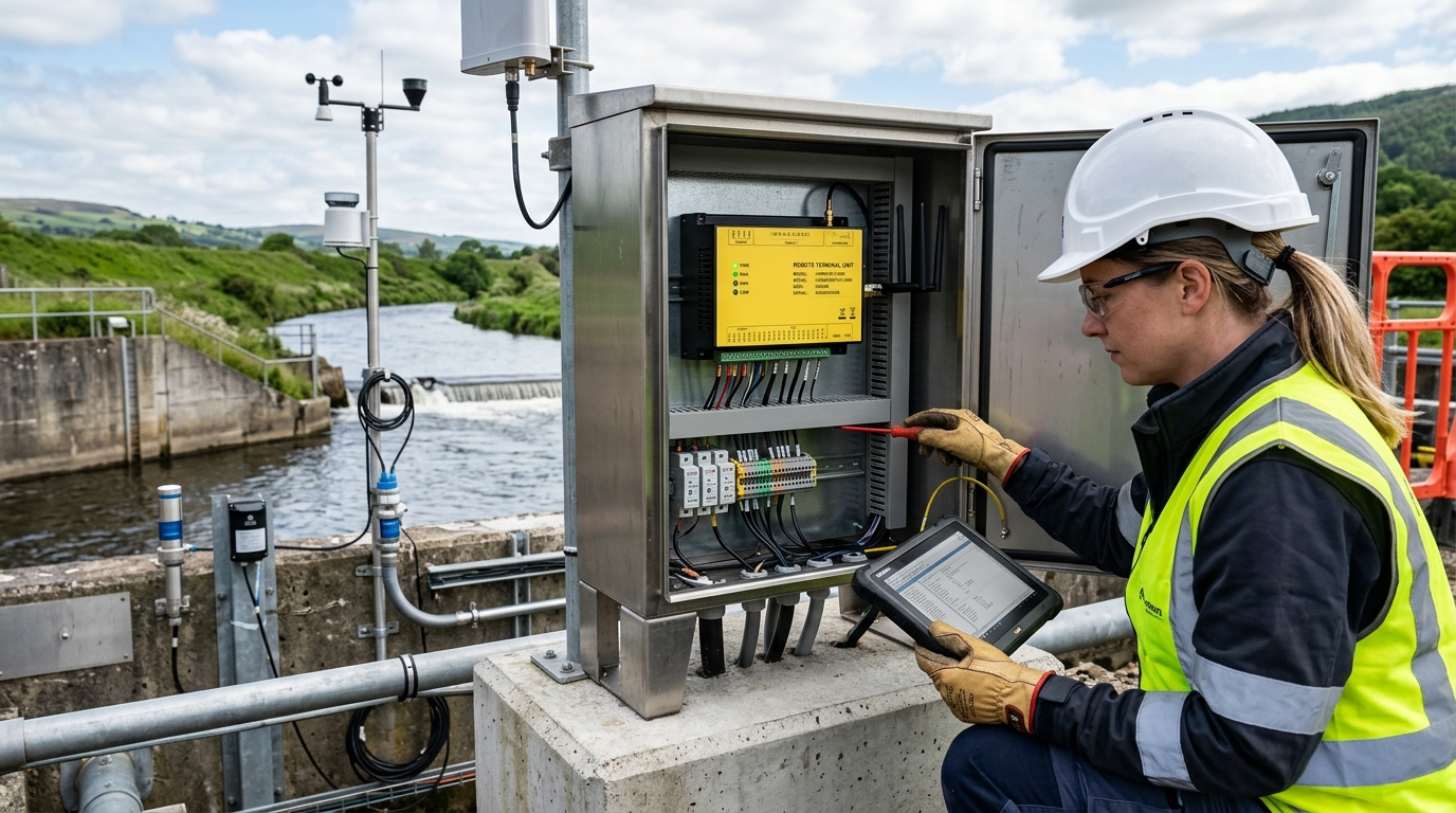
In scenarios such as water resources informatization, flash flood disaster monitoring, and modernization of irrigation districts, RTU telemetry terminals undertake the fundamental tasks of on-site sensor data acquisition, local storage, remote transmission, and anomaly reporting. Compared with ordinary industrial control gateways, RTUs usually need to adapt to environments without mains power, outdoor exposure, high humidity, lightning storms, and unstable communication conditions. Therefore, the quality of installation, commissioning, and maintenance directly affects the data integrity rate and online rate.
From the perspective of Yicai Technology's industry observation, this article takes the commonly used Hero V9 RTU telemetry terminal as an example, focusing on data acquisition, remote transmission, and water conservancy application requirements, to compile a set of practical and implementable operation guides. The parameters in the text refer to typical engineering configurations; actual projects should be based on the equipment nameplate, design drawings, and platform protocols.
II. Pre-installation Preparation: Verify Points, Power Supply, and Interfaces First
Before installation, point verification should be completed first. Water conservancy stations are usually distributed near reservoir spillways, channel flow measurement cross-sections, river water level wells, rainfall fields, or pump stations. The installation location should meet three conditions:
- Measurement Convenience: Convenient for sensor measurement and not affected by floating objects, backflow, or human damage.
- Signal Stability: No obvious metal obstruction around the antenna, ensuring stable 4G signal access.
- Solar Exposure: Sufficient sunlight for the solar panel, avoiding shading from tree shadows, dam bodies, or buildings.
Power Configuration Recommendations (Hero V9)
- Input Range: DC9~36V (Typical systems: DC12V or DC24V).
- Battery: For solar power, configure a 12V/20Ah or above lithium iron phosphate or gel battery.
- Autonomy: Design for 3 to 7 continuous rainy days.
- Power Consumption: Average daily consumption for integrated stations is typically 1~3W.
Interface verification is equally critical. Common sensors include submersible level transmitters, radar water level meters, tipping bucket rain gauges, flow velocity meters, and water quality probes. The Hero V9 generally features analog input, digital input, RS485 serial port, and relay output. Before installation, verify:
- Whether 4-20mA sensors use two-wire or four-wire systems.
- The baud rate, data bits, parity bits, and station numbers of RS485 devices.
- Whether the pulse output of the rain gauge needs debouncing.
- Whether the DO output capacity meets load requirements for pumps and valves.
III. Installation Steps: Fixing, Wiring, Waterproofing, Lightning Protection, and Grounding
1. Equipment Fixing
Install on a pole, wall, or dedicated cabinet. Keep the enclosure bottom ≥1.2m from the ground to avoid soaking and human touch. Use IP65+ enclosures with waterproof connectors. Ensure internal space for battery/SIM replacement.
2. Power Wiring
Measure voltage before wiring. Use RVV2×1.5mm² or RVV2×2.5mm² cables. Increase cross-section if length >30m. Install a fuse or DC circuit breaker rated at 1.5-2x max power consumption.
3. Sensor Wiring
Analog (4-20mA): Connect shield layer at one end (enclosure side) to avoid ground loops.
RS485: Connect A to A, B to B. Use twisted pair shielded cable. Add 120Ω resistor if distance/interference requires.
Rain Gauge: Connect pulse signal to DI terminal. Set coefficient in software (e.g., 0.5mm/pulse).
4. Antenna & Communication
Mount 4G magnetic antenna outside the enclosure or on top of the pole, away from power lines. Ensure clear line of sight for BeiDou/Short Message antennas. Tighten connectors and waterproof them.
Lightning Protection & Grounding
Water conservancy stations are high-risk areas for lightning strikes. Solar brackets, poles, enclosures, and antenna mounts must connect to the grounding system.
- Grounding Body: Galvanized angle steel or copper-clad steel.
- Resistance: Recommended ≤10Ω; important stations <4Ω.
- Surge Protection: Install surge protectors on signal lines entering the enclosure and DC surge protective devices at the power end.
IV. Commissioning Methods: Parameter Configuration, Data Acquisition, and Remote Transmission Verification
Commissioning starts with local configuration. After powering on, observe indicators (power, running, communication). Use a serial cable, Bluetooth tool, or platform remote config to verify device number, SIM card, clock, channels, and communication parameters.
Data Acquisition Configuration
Set sensor type, range, unit, and filtering parameters per channel. For example, for a 0-10m submersible transmitter (4-20mA), enable 3-5 times average filtering. If water levels fluctuate significantly, set a variable amplitude additional reporting threshold (e.g., report immediately if change >5cm) to capture flood peaks.
Remote Transmission Configuration
Configure the platform protocol (MQTT, HTTP, TCP, etc.). Set data center address, port, APN, and credentials.
- Reporting Cycle: Typically every 15-30 minutes; shorten to 5-10 minutes during flood season.
- Event Reporting: Rainfall stations can report additionally upon cumulative thresholds (e.g., every 1mm or 5mm).
Verification Checklist
- Data Accuracy: Compare RTU values with multimeter measurements (e.g., 12mA = 5m water level).
- Communication Quality: Check RSRP (≥-95dBm) and SINR (≥5dB). Replace high-gain/directional antennas if weak.
- Offline Caching: Simulate network failure to ensure local caching (≥30 days) and auto-retransmission upon recovery.
V. Daily Maintenance: Periodic Inspection, Data Quality, and Equipment Health Management
Long-term stability relies on institutionalized maintenance. Establish a "remote inspection + regular on-site maintenance" mechanism.
Remote Inspection (Daily/Weekly)
- Online status and latest data time.
- Battery voltage and signal strength.
- Abnormal alarms.
On-Site Maintenance (Quarterly)
- Check enclosure sealing, condensation, and insect traces.
- Inspect wiring terminals for looseness/oxidation.
- Clean solar panels (dust, bird droppings).
- Verify antenna fixing and feeder condition.
- Clear weeds/silt around sensors.
Data Quality & Battery Management
Analyze sudden data changes against rainfall and gate dispatch records. For battery health, maintain float voltage between 13.2V-14.4V (for 12V systems). If static voltage drops below 11.8V, check solar output and battery capacity. Set low-voltage alarms (e.g., <11.5V) for advance maintenance.
Regularly backup equipment parameters (device IDs, SIMs, IP/domain, ports, channel mapping, firmware versions) and maintenance logs to ensure traceability.
VI. Common Fault Troubleshooting: Quickly Locate Power, Sensors, and Communication Links
Troubleshoot in the order: Power → Acquisition → Communication → Platform.
Fault Type 1: Device Offline / No Power
Check battery voltage. If low, inspect solar panel shading/wiring. If voltage normal but no start, check fuse, breaker, polarity, and contacts. Repeated restarts may indicate power fluctuations or short circuits.
Fault Type 2: Missing Data / Abnormal Values
All channels: Check protection mode, acquisition task, and sensor power.
Single channel: Fixed 0/full scale? Check sensor power, open circuit, or polarity. Fluctuating data? Check shielding, interference, or loose connections.
RS485: Check A/B reversal, station conflicts, baud rates, and bus driving capacity.
Fault Type 3: Transmission Issues
Check SIM balance, APN, and platform address/port. If signal is good but data fails, check packet capture/logs. Frequent drop-offs may relate to instantaneous voltage drops or antenna contact issues.
Fault Type 4: False Alarms / Lag
False rainfall? Adjust debounce time, add nets, check grounding. Level lag? Check sensor position, siltation, or filtering parameters. Time inconsistency? Enable NTP/BeiDou sync.
Tips: Maintain a "minimum system test" setup (Power + RTU + Known Sensor + Valid SIM) to isolate faults quickly. Keep spare parts for critical stations.
VII. Application Cases: Practical Points in Irrigation District and Reservoir Monitoring
Case 1: Irrigation District Channel Monitoring
- Setup: 16 points using Hero V9, submersible transmitters, solar, and 12V batteries.
- Challenge: Weak 4G signals at scattered locations.
- Solution: Installed high-gain antennas at 3 weak sites, raised height to 6m. Improved RSRP to -92dBm.
- Result: 99.2% online rate, 98.7% data integrity over 3 months. Early detection of branch shading via low-voltage alarms.
Case 2: Small Reservoir Integrated Station
- Setup: Hero V9 connected to tipping bucket rain gauge and radar water level meter.
- Configuration: 10-min reporting in flood season. Encrypted reporting when rainfall >20mm/hr or level exceeds limit.
- Fault Found: Low rain gauge count due to leaf blockage in inlet. Cleaned and restored.
These cases demonstrate that RTU project success depends on site survey, interface matching, link verification, and closed-loop maintenance—not just the device itself.
VIII. Conclusion and Outlook: Moving from Single-point Telemetry to Standardized O&M
With the advancement of water conservancy digitalization, RTUs are evolving into intelligent edge nodes with self-diagnosis and multi-link capabilities. Future trends emphasize high-frequency reliable acquisition and diverse transmission methods (4G/5G/BeiDou backup).
For engineering and O&M units, standardized installation, rigorous commissioning records, and normalized maintenance are core quality indicators. By refining these processes with carriers like the Hero V9, we can ensure accurate, timely, and traceable monitoring data, providing robust support for flood control and water resource management.

