Complete Guide to Installation and Commissioning of Doppler Flow Meters (with FAQs)
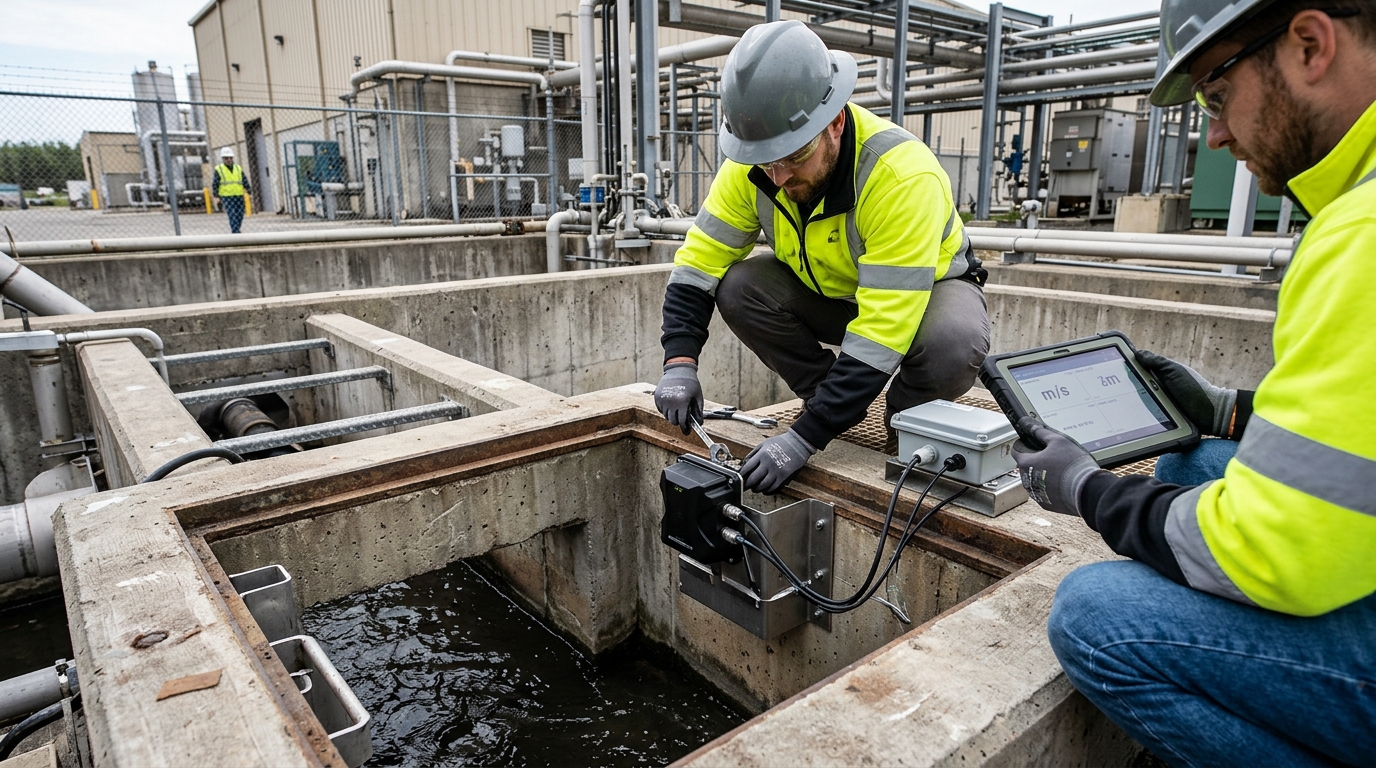
With increasing projects in urban drainage, irrigation district metering, ecological water replenishment for rivers and lakes, and industrial wastewater open-channel monitoring, field applications of Doppler flowmeters in complex water environments are becoming increasingly frequent. Unlike closed-pipe flowmeters, open-channel and partially full pipe conditions are often accompanied by water level fluctuations, changes in suspended solids, obstruction by floating debris, sediment deposition, and other issues. From the perspective of field engineers and O&M teams, this article summarizes installation, commissioning, maintenance, and troubleshooting methods for non-contact Doppler flowmeters, with emphasis on practical points for coordinated operation of velocity, water level, and integrated cameras, for project selection, construction acceptance, and long-term operation reference.
I. Measurement Principle and Applicable Boundaries
The basic principle of a Doppler flowmeter is to emit ultrasonic, microwave, or laser signals into the water body or water surface, and receive echoes returned by scatterers such as suspended particles, bubbles, and surface disturbances. When scatterers move with the flow, the echo frequency experiences a Doppler shift relative to the transmitted frequency, and the shift amount is related to flow velocity. Non-contact devices usually install the sensor above or laterally above the channel; the acoustic beam does not directly contact the water body, but completes velocity measurement through the water surface, surface-layer suspended solids, or echo scatterers.
Water level measurement commonly uses radar level transmitters, ultrasonic level transmitters, or pressure level transmitters. For projects emphasizing non-contact maintenance, radar level transmitters are more convenient for avoiding deposition and corrosion caused by long-term probe immersion. Integrated camera modules are used to record water surface status, floating debris accumulation, personnel intrusion, equipment obstruction, algae blooms, and other conditions, providing image evidence for velocity and water level data. In actual engineering, velocity, water level, and camera are not simply additive; they together constitute the basis for data quality judgment.
Note: Non-contact velocity measurement often reflects surface or beam coverage area velocity. It needs to be combined with channel cross-section, bed slope, and velocity profile coefficient (often 0.75 to 0.95) to convert to cross-section average velocity.
From the perspective of applicable conditions, non-contact Doppler flowmeters are more suitable for water bodies containing suspended solids or bubbles, such as municipal sewage, first flush rainwater, irrigation channels, and partially full pipe drainage. It is generally recommended that water body solids content be greater than 50 mg/L, water depth be 0.1 m to 3 m, velocity be 0.05 m/s to 5 m/s, and channel width be 0.3 m to 3 m. Common velocity accuracy can be controlled within ±1% full scale, or better than ±0.03 m/s; water level resolution is typically 1 mm, with error controlled within ±1 mm to ±3 mm.
II. Selection and Field Survey
A field survey must be completed before selection. Engineers should measure channel width, bed slope, roughness, normal water level, maximum water level, and minimum water level, and record upstream gates, drops, bends, branch pipe inflows, and other flow disturbance sources. The installation location should preferably be in a straight channel segment with stable flow, open water surface, and no strong vortices. It is generally recommended to be at least 5 to 10 channel widths from upstream gates or elbows, and at least 3 to 5 water depths from downstream drops. If the site cannot meet this requirement, flow straighteners, energy dissipation plates, or extended measurement reaches should be provided.
Fluid Conditions Check
Collect at least 5 water samples. Observe suspended solids, oil, foam, algae, and floating debris. For clear water or overly calm surfaces, Doppler echoes may be weak. Consider adjusting transmit power, receive gain, incident angle, or using laser Doppler/millimeter-wave radar.
Power & Communication
Solar setups: 10W-20W panel + 50Ah-100Ah battery. Comm options: 4G, NB-IoT, LoRa, Ethernet. Camera: 2MP-4MP, IP66+, IR fill light. Sensor main unit: IP68 or IP66+.
Selection parameters should leave margin: velocity range should be configured at 1.2 to 1.5 times the historical maximum velocity, water level range at the highest water level plus 0.5 m, and radar level transmitter blind zone should be less than 0.3 m to 0.5 m.
III. Installation Steps
Before installation, prepare stainless steel posts or portal brackets. Common post diameter should be no less than 40 mm, wall thickness no less than 2 mm. Equipment should include a spirit level, angle ruler, laser distance meter, multimeter, waterproof sealant, grounding wire, and conduit. The bracket should be securely fixed and able to resist wind vibration and flow impact. If a concrete foundation is used, foundation dimensions can be designed according to wind load and soil conditions; a common practice is 400 mm square, depth 400 mm to 600 mm, with reserved grounding terminals. Grounding resistance should preferably be controlled below 4Ω; surge protectors should be added in lightning-prone areas.
- Velocity Sensor: Install above or laterally above the channel, 0.3 m to 1.2 m above water surface. Acoustic beam incident angle: 30° to 45°. Align beam center with main flow area, avoiding metal bottoms or strong reflectors. Record actual height, pitch, and azimuth.
- Water Level Sensor: Install at same/adjacent cross-section as velocity sensor. Radar probes point vertically down; avoid mist/foam zones. Pressure probes at bottom, away from impact. Provide manual staff gauge for verification.
- Integrated Camera: Install on post or crossbeam. Depression angle: 30° to 60°. Cover water surface, sensors, and channel. Avoid backlight; use WDR if necessary. Ensure lens cleanliness and consider heating demisting for cold regions.
- Cable Routing: Separate strong/weak current. Use conduits/bundles. Junction boxes face downward. Reserve 5%-10% slack with drip loops. Ground all metal parts/shields.
After installation, take photos for archiving, recording sensor height, angle, wiring, supply voltage, and communication signal strength.
IV. Commissioning Methods
The first step is to confirm power supply and communication. Read device voltage, current, signal strength, and firmware version. For solar systems, check battery voltage and controller status. For 4G, test signal strength and APN configuration. Set sampling interval to 1 s to 5 s during commissioning to observe instantaneous fluctuations; adjust to 10 s to 60 s for formal operation.
Key Calibration Steps
- Static Commissioning: With stopped flow/calm surface, velocity should be ~0 m/s. Water level drift < 2 mm vs staff gauge. Apply zero correction if needed.
- Angle Calibration: Recheck pitch/azimuth with level/angle ruler. Deviation > 1° requires refixing. Verify beam covers main flow band.
- Water Level Calibration: Multi-point comparison (low/med/high levels). Error < 5 mm or 0.5% FS. Account for foam/steam/rain effects on radar.
- Velocity Verification: Use handheld current meter/ADCP/float method. Three-point method (left/center/right). Field time > 10 mins. Error target: 5%-10%. Recalculate coefficients if error is large.
Cross-section parameter configuration is key. Input channel width, bed elevation, side slope, roughness, weir/flume type, and max/min levels. For rectangular channels, Flow ≈ Area × Average Velocity. For Parshall flumes/weirs, use stage-discharge rating curves. Run system continuously for 24 hours post-commissioning; ensure data completeness ≥ 98%.
V. Routine Maintenance
Use data curves and field images as clues. Check trends weekly. Focus on abrupt water level changes, long-term zero velocity, abnormal cumulative flow, and camera obstructions. Set alarms for water level deviation ±0.2 m, velocity > 1.5x max, no data for 30 mins, or black/blurry images.
| Frequency | Tasks |
|---|---|
| Monthly | Clean probes/lenses/solar panels. Check bolts/connectors/grounding. Retain 7 days video / 30 days event images. |
| Seasonal | Spring: Clear algae/catkins. Summer: Lightning/grounding checks. Autumn: Clear leaves/debris. Winter: Battery/heating/icing checks. |
| Annual | Systematic calibration (zero point, velocity, cross-section). Archive records including weather, errors, and corrective actions. Update equipment ledger. |
VI. Common Fault Troubleshooting
No Echo / Velocity at 0
Causes: Low solids, calm surface, beam obstruction, insufficient gain. Action: Check camera view, clean probe, adjust gain/power. If clear water persists, consider contact transducer or adding disturbance (not pollutants).
Water Level Drift
Radar: Susceptible to foam/steam/rain. Use median filtering/wave-dampening plates. Pressure: Clogging/temp/atmospheric issues. Clean vent tube/recalibrate.
Abnormal Velocity (High/Low)
Surface velocity > average. Floating debris/wind waves cause high readings. Beam covering shallow banks causes low readings. Recalculate profile coefficient using staff gauge/current meter data.
Large Cumulative Flow Error
Check water level zero drift, bed elevation changes (deposition), width entry errors, and packet loss. Verify data gap-filling logic avoids abnormal interpolation.
Camera Issues (Blurry/Black/Sync)
Clean lens/check focus/seal. Black screen: Power/network/IR failure. Time sync: Enable NTP, check clock/timezone/upload delay.
Communication Interruption
Check voltage, SIM, antenna, signal strength. Weak 4G: High-gain antenna/height adjustment. LoRa/NB-IoT: Gateway coverage/frequency. Solar: Under-voltage due to rain/load.
VII. Case Studies
Municipal Sewage Open Channel
Specs: Width 0.8m, Depth 0.35-0.95m, Velocity 0.2-2.8 m/s.
Solution: Non-contact Doppler + Radar Level + 2MP Camera. Solar powered (10W/50Ah), 4G comm. Angle 40°, Height 0.8m.
Result: 4.8% avg velocity error. 99.2% data completeness over 30 days. 25 mins monthly maintenance.
Irrigation District Channel
Specs: Width 1.5m, Depth 0.2-1.3m, Solids 80-300 mg/L.
Solution: Integrated V/W/Camera. Camera angle 45°. Initial drift due to foam/light reflection.
Result: Adjusted radar params + wave-dampening plate reduced error from 8mm to 3mm. <5% cumulative flow deviation over 6 months. Reduced manual patrols.
VIII. Outlook: Multi-Sensor Fusion and Data Governance
Doppler flowmeters are evolving from single devices into systems integrating velocity, water level, camera, water quality edge sensing, and remote diagnostics. Non-contact measurement reduces maintenance pressure, while integrated cameras provide traceable image evidence. Future trends include edge computing and image recognition for automatic identification of debris, intrusion, icing, and algae, triggering cleaning or data quality down-weighting.
However, technological evolution cannot replace field fundamentals. No matter how sensor accuracy improves, installation angle, cross-section parameters, water level reference, communication quality, and periodic verification remain the foundation of reliable data. For procurement, construction, and O&M personnel, establishing unified installation records, commissioning records, and fault ledgers is more important than simply pursuing device parameters. As open-channel metering expands, managing non-contact measurement, velocity conversion, water level calibration, and camera linkage as a complete system becomes essential.

